- Physics Lab Equipment
- Chemistry Lab Equipment
- Biology Lab Equipment
- Anatomical Lab Equipment
- Learning
- Educational Lab Equipment
- Magnets
- Agriculture
- Astronomy
- Earth Science
- Geography Lab Equipment
- Safety Lab Coat
- Laboratory
- Meteorological
- Electricity & Magnetism
- Heat
- School Lab Equipment
- Lab Glassware
- Science Lab Equipment
- Tvet Lab Equipment
- Robotics Kits Supplier and Manufacturer for Schools India
- Math Lab Equipment Manufacturers and Exporters in Ambala
- STEM Kits Manufacturers and Supplier India
- Engineering Lab Equipment
- Hospital Lab Equipment
- Water, Sanitation & Hygiene Supplies
- Cold Chain, Solar & Communication Equipment
- Nutrition
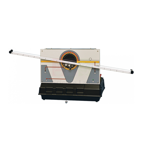
Ball and Beam Apparatus
Ball and Beam Apparatus (Product Code: SLE/ETC/03) is an unstable-system control trainer used to teach active feedback control of a naturally unstable double integrator in control engineering laboratories. A steel ball rolls on two parallel tensioned wires carried by a centre-pivoted beam, while a servo motor tilts the beam and sensors report beam angle and ball position. The apparatus comes from Jain Scientific Equipments Pvt Ltd (ScienceLab), an OEM manufacturer, and is made at its own factory in Ambala, India.
Key Details
| Parameter | Detail |
|---|---|
| Ball | Steel ball, free to roll on two parallel tensioned wires |
| Beam | Carries the wires and pivots at its centre |
| Actuator | Servo motor controlling the beam angle |
| Sensors | Measure the beam angle and the ball position |
| System type | Double integrator — naturally unstable |
| Control method | Active feedback control using phase-advance methods |
| Real-world analogy | A rocket or missile during launch, which needs active control to prevent it going unstable and toppling over |
| Product code | SLE/ETC/03 |
| Manufacturer | Jain Scientific Equipments Pvt Ltd (ScienceLab) — OEM |
| Country of origin | India (made in Ambala, Haryana) |
What Is the Ball and Beam Apparatus Used For?
The basic control problem is to vary the beam angle so the ball stays at, or moves to, a chosen position. Left alone, the ball simply rolls to one end — which is exactly why the apparatus is valuable: students must design a controller that actively stabilises the system rather than merely speeding up one that is already stable.
A common teaching sequence starts with an inner loop on beam angle through the servo motor, followed by an outer ball-position loop using phase-advance (lead) compensation. The comparison with launch-vehicle stability makes the theory memorable for aerospace, mechatronics and electrical students, and gives engineering lab equipment collections a very visible demonstration of instability.
OEM Manufacturer
ScienceLab is the brand under which Jain Scientific Equipments Private Limited sells its own laboratory equipment, and the company is the OEM for the Ball and Beam Apparatus. The unit is fabricated and assembled at its licensed factory in Saha, Ambala, Haryana, India. Because buyers deal with the manufacturer directly, questions about a replacement ball, wires or other spares can simply be put to us. Learn more on the company profile.
Related Control & Process Engineering Trainers
These trainers extend the stability and servo topics introduced by the Ball and Beam Apparatus.
- Ball and Hoop Apparatus — servo position control with a ball that behaves like a pendulum
- Servo Trainer — d.c. servo speed and position control with adjustable non-linear effects
- Controller — phase-lead, proportional, integral and PID blocks for building the stabilising loop
- Digital Interface — computer input/output for running digital controllers
Find all servo, process and control apparatus in the Control & Process Engineering Trainers category.
Frequently Asked Questions
Why is the Ball and Beam Apparatus unstable?
The Ball and Beam Apparatus is a double integrator: tilting the beam makes the ball accelerate, and its position keeps changing unless the angle is corrected. This makes it naturally unstable, so it needs active feedback control using phase-advance methods.
What sensors are fitted to the Ball and Beam Apparatus?
The Ball and Beam Apparatus has sensors that measure the beam angle and the ball position. A servo motor controls the beam angle, giving students both the measurements and the actuator needed to close a position-control loop.
What does the ball roll on in the Ball and Beam Apparatus?
In the Ball and Beam Apparatus, a steel ball rolls freely on two parallel tensioned wires. The wires sit on a beam that pivots at its centre, so changing the beam angle moves the ball along the wires.
What real systems does the Ball and Beam Apparatus represent?
The Ball and Beam Apparatus represents the control problems of unstable systems, for example a rocket or missile during launch, which needs active control to stop it going unstable and toppling over.
Who manufactures the Ball and Beam Apparatus?
Jain Scientific Equipments Pvt Ltd (ScienceLab) manufactures the Ball and Beam Apparatus as the OEM at its own licensed factory in Saha, Ambala, Haryana, India. Buying from the maker means a replacement ball or wire can be requested from the same source.
Can the Ball and Beam Apparatus be ordered for several lab benches?
Yes. The Ball and Beam Apparatus can be quoted as a single unit or for multiple benches, for buyers in India and international markets. Share the quantity and delivery location through our contact page so the manufacturer can prepare the quotation.
Request a Quote
To receive a price for the Ball and Beam Apparatus, use the contact page or add it to the enquiry cart. Your quotation is sent directly by the manufacturer, ScienceLab.
Last updated: 24 September 2026

CRDI Diesel Engine SANTAFE D Engine, Stand
The CRDI Diesel Engine SANTAFE D Engine, Stand carries a 2,000cc CRDI BOSCH D engine, the same unit as fitted to the real vehicle, precisely cut so learners can watch pistons, valves and crank move. A 220V motor under an engine speed controller turns it. The fuel, cooling and lubrication systems are painted in separate colours, and the steel frame rolls on 4 braked wheels.
SANTAFE D engine stand specifications
| Parameter | Detail |
|---|---|
| Engine | 2,000cc CRDI BOSCH D engine, same as the real-vehicle unit, precisely cut to show internal movement |
| Engine ancillaries | Starting motor, generator, air conditioner compressor, intake manifold, torque converter |
| Systems shown | Fuel system, cooling system, lubrication system |
| Drive | 220V motor with engine speed controller |
| Electrical protection | Safety breaker, emergency switch, safety fuse |
| Stand | Steel frame with heat treatment painting; 4 wheels with brakes |
| Finish | Each incised section painted in a different colour |
| Weight and size | Approx. 250 kg; approx. 650 × 500 × 1,500 mm |
| Training contents | Attaching and detaching the generator and starting motor; replacing the timing belt and other belts; replacing the oil filter |
| Product code | SLE/ATE/15 |
| Minimum order | 10 units |
| Dispatch | Usually within 7 to 10 working days |
| Manufacturer | ScienceLab (Jain Scientific Equipments Pvt Ltd), Ambala, India |
Timing, belt and systems practicals on the D engine stand
Valve timing study. Set the speed controller to its slowest and follow one cylinder through a full cycle. Students note the piston position when each valve starts to open and when it closes, then draw a valve timing diagram. At higher speed, a xenon stroboscope seems to freeze the crank pulley and valve train so the same events can be checked.
Timing belt replacement. With the drive isolated at the safety breaker, trainees align the crankshaft and camshaft marks and change the belt. They set the tension, turn the engine by hand through two full turns and confirm that the marks line up again before the stand is switched on.
Starting motor and generator service. A group unbolts the starting motor and generator, inspects the mountings and refits them, tightening each bolt in turn. Before the stand is switched on again, they check that no tool or loose part is left near the belts and pulleys.
Colour-coded systems trace. Using the painted sections, students trace fuel, cooling and lubrication passages in turn and name each part they pass. Beginners can first study the basic cycle on a section model of a four-stroke diesel engine.
Frequently Asked Questions About the CRDI Diesel Engine SANTAFE D Engine, Stand
When should the timing belt on a diesel engine be replaced?
At the distance or age the engine maker sets, whichever comes first, even if the belt still looks good. Between changes, inspect it for cracks, glazing, missing teeth, oil contamination and frayed edges. The tensioner and idler pulleys are usually renewed at the same time.
What happens if the timing belt breaks on a diesel engine?
The camshaft stops while the crankshaft keeps turning. Diesel engines run very small clearances between pistons and valves, so the pistons usually strike any valves left open. The result is bent valves and often damaged pistons or guides, which means a major repair rather than just a new belt.
How is the timing belt different from the other belts on this engine?
The timing belt is toothed and runs behind a cover, keeping crankshaft and camshaft in step. The outer ribbed belt drives accessories such as the generator and air conditioner compressor. The training contents cover both, but only the timing belt needs its marks aligned before fitting.
What is valve overlap, and can students see it on this engine?
Valve overlap is the short period around top dead centre, at the end of the exhaust stroke, when the inlet and exhaust valves are both open. Outgoing exhaust helps draw in fresh air. With the motor turning the cut engine slowly, students can watch for the moment both valves of one cylinder stand open together.
Why is the oil filter changed together with the engine oil?
The lubrication system pumps oil from the sump through the filter to the bearings, camshaft and other moving parts. The filter traps soot and wear particles, and once it clogs, its bypass opens and dirty oil circulates. Changing both together keeps fresh oil clean for longer.
Why is a torque converter fitted to this engine stand?
It shows how this engine couples to an automatic transmission. The torque converter is driven from the rear of the crankshaft in place of a clutch and flywheel, so learners see the drive take-off point of an automatic-transmission vehicle on the same stand.
Diesel engine and CRDI teaching units
- CRDI Diesel Engine Stand, Motor Type
- CRDI (Common Rail Direct Injector) System
- Diesel Engine Fault Diagnosis Training Equipment Auto Fault
- Section Model Of Four-Stroke Diesel Engine
- 4 Stroke Diesel Engine
- Diesel Fuel Injection System VE pump
To request a quotation, send the product name, code and quantity through our contact page or add the item to your enquiry cart.
Last updated: 20 November 2026

CRDI Diesel Engine Stand, Motor Type
The CRDI Diesel Engine Stand, Motor Type is a sectioned 2,900cc CRDI Delphi diesel engine that a 220V motor runs automatically, the way it turns in a vehicle. An engine speed controller sets the pace, and an LED lamp turns on at ignition. The starting motor, generator, air conditioner compressor and intake manifold stay fitted, and the steel frame rolls on 4 braked wheels.
Motor-type CRDI engine stand specifications
| Parameter | Detail |
|---|---|
| Engine | 2,900cc CRDI Delphi engine, sectioned by precise cutting |
| Engine equipment | Starting motor, generator, air conditioner compressor, intake manifold |
| Systems | Fuel system, cooling system, lubrication system |
| Operation | Automatic operation type, driven by 220V motor with engine speed controller; LED lamp turns on at ignition |
| Protection | Safety breaker, emergency switch, safety fuse |
| Stand | Steel frame with heat treatment painting; 4 wheels with brakes |
| Finish | Each engine part painted specifically; incised sections in different colours |
| Weight and size | Approx. 150 kg; approx. 700 × 650 × 1,500 mm |
| Training contents | Attaching and detaching the generator and starting motor; replacing the timing belt and the other engine belts; replacing the oil filter |
| Product code | SLE/ATE/16 |
| Minimum order | 10 units |
| Dispatch | Usually within 7 to 10 working days |
| Manufacturer | ScienceLab (Jain Scientific Equipments Pvt Ltd), Ambala, India |
Engine cycle and service practicals on the motor-type stand
Four-stroke cycle watch. Run the engine slowly on the speed controller and follow one cylinder through suction, compression, power and exhaust. Students call out each stroke as the piston and valves move, and mark where fuel would enter near the top of compression. Newer groups can start on a simpler four-stroke diesel engine model.
Working out the firing order. Students number the cylinders, then watch the cut crank and valves to find the order in which each cylinder reaches its power stroke. They confirm it over a second full cycle and explain how that order spreads the power impulses along the crankshaft.
Service round. With the drive off at the safety breaker and the emergency switch within reach, each group in turn slackens and removes the generator, refits it and re-tensions its belt. The next group renews the oil filter, and a third detaches and refits the starting motor.
Whole engine and injection hardware. Pair the stand with the CRDI pump and nozzle set. Students find where the high-pressure pump, rail and injectors sit on the cut engine, then study a sectioned injector nozzle up close on the bench.
Frequently Asked Questions About the CRDI Diesel Engine Stand, Motor Type
How does a diesel engine ignite its fuel without spark plugs?
By heat of compression. Only air enters on the suction stroke, and squeezing it on the compression stroke makes it hot enough to light diesel. Fuel is injected near top dead centre and ignites by itself. On this stand, an LED lamp turns on at ignition.
Why does a multi-cylinder diesel follow a firing order?
So that power strokes are spread evenly along the crankshaft. Firing neighbouring cylinders one after another would load one end of the crank and its bearings heavily and make the engine run rough. A good firing order balances the forces, smooths running and shares heat across the block.
What causes the knocking sound of a diesel engine?
Ignition delay. Fuel injected in the short gap before combustion starts collects in the cylinder, then burns all at once, giving a sharp pressure rise that is heard as knock. A cold engine or poor fuel lengthens the delay, and common rail systems shorten it with a small pilot injection.
Why is a diesel hard to start in cold weather, and what do glow plugs do?
Cold metal draws heat from the compressed air, so it may not get hot enough to light the fuel, and the engine cranks long and coughs. Glow plugs heat the combustion chamber before and during starting. A failed glow plug in one cylinder shows as rough running until the engine warms up.
Can a weak battery or generator cause hard starting on a diesel?
Yes. A diesel must crank fast enough to build compression heat, and a weak battery turns it too slowly. A generator that is not charging lets the battery run down between starts. Check battery voltage and generator output with a digital multimeter before suspecting the fuel system.
How is the engine stand moved between rooms?
It weighs about 150 kg on a steel frame with 4 wheels, each with a brake. Release the brakes, push it with two people, and lock every wheel again before the motor is started. Its overall size is about 700 × 650 × 1,500 mm.
Diesel engine and fuel injection trainers
- CRDI Diesel Engine SANTAFE D Engine, Stand
- CRDI (Common Rail Direct Injector) System
- CRDI Diesel Engine Power Train System F/R Type
- Diesel Fuel Injection System VE pump
- Diesel Engine Fault Diagnosis Training Equipment Auto Fault
- Section Model Of Four-Stroke Diesel Engine
To request a quotation, send the product name, code and quantity through our contact page or add the item to your enquiry cart.
Last updated: 20 November 2026
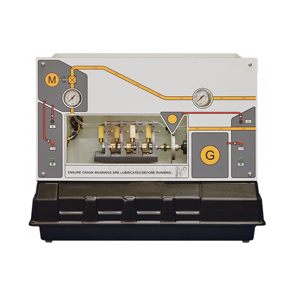
Engine Speed Control Apparatus
Engine Speed Control Apparatus (Product Code: SLE/ETC/04) is a speed-regulation trainer used to show the problems of controlling rotating machines, especially non-linear control systems, in engineering laboratories. It uses a scale-model engine driven by compressed air for safety, a motorised valve that sets engine speed, and a d.c. generator that loads the engine output. Jain Scientific Equipments Pvt Ltd (ScienceLab), an OEM manufacturer, produces it at its own factory in Ambala, India.
Key Details
| Parameter | Detail |
|---|---|
| Engine | Scale-model engine driven by compressed air, for safety |
| Compressed air | Not supplied — provided by the user's laboratory |
| Speed actuator | Motorised valve adjusted to regulate engine speed |
| Load | d.c. generator connected to the engine output |
| Basic control task | Regulate engine speed under load |
| Advanced experiments | Non-linearity compensation using dither signals; multiple loop and minor loop control; system modelling from step response information; P+I control and root locus methods |
| Product code | SLE/ETC/04 |
| Manufacturer | Jain Scientific Equipments Pvt Ltd (ScienceLab) — OEM |
| Country of origin | India (made in Ambala, Haryana) |
What Is the Engine Speed Control Apparatus Used For?
The basic purpose is to adjust the motorised valve so the engine holds a set speed while the d.c. generator loads it. Valves and air-driven engines seldom respond in a straight line, so students meet non-linear behaviour directly and learn why a controller tuned at one operating point may struggle at another.
Advanced sessions use dither signals to compensate for non-linearity, compare single-loop control with multiple-loop and minor-loop structures, build a model from step-response data and design P+I controllers with root-locus methods. Running the model engine on compressed air rather than fuel keeps the exercise safe for teaching, which makes it a practical addition to engineering lab equipment for mechanical, automotive and control courses.
OEM Manufacturer
Jain Scientific Equipments Private Limited — known to customers as ScienceLab — is the OEM for the Engine Speed Control Apparatus and builds it at its own licensed factory at Saha, Ambala, Haryana, India. Engineering colleges, training centres, dealers and importers order directly from the company that makes it, so quotations, repeat orders and spare-part questions are all handled at source. Visit the ScienceLab profile to learn more.
Related Control & Process Engineering Trainers
These trainers complement the speed-control work done on the Engine Speed Control Apparatus.
- Servo Trainer — d.c. servo speed and position control with generator loading
- Coupled Drives Apparatus — speed and tension control of two belt-coupled motors
- Controller — proportional, integral and PID blocks for P+I speed loops
- Digital Interface — passes step-response signals to a computer for system modelling
Browse the Control & Process Engineering Trainers category for the full range.
Frequently Asked Questions
Is compressed air supplied with the Engine Speed Control Apparatus?
No. The Engine Speed Control Apparatus runs its scale-model engine on compressed air for safety, but the compressed air is not supplied. Your laboratory needs its own air source; discuss the requirement with us when you enquire.
How is the engine loaded on the Engine Speed Control Apparatus?
A d.c. generator connects to the engine output of the Engine Speed Control Apparatus and loads the engine, so students can test how well their controller holds speed when the load changes.
Which advanced experiments can be run on the Engine Speed Control Apparatus?
Advanced experiments on the Engine Speed Control Apparatus include non-linearity compensation using dither signals, multiple-loop and minor-loop control, system modelling from step response information, and P+I control with root locus methods.
What sets the engine speed on the Engine Speed Control Apparatus?
Engine speed on the Engine Speed Control Apparatus is set by a motorised valve. Adjusting the valve changes the air reaching the scale-model engine, and the control task is to regulate speed while the generator applies load.
Who manufactures the Engine Speed Control Apparatus?
The Engine Speed Control Apparatus is manufactured by Jain Scientific Equipments Pvt Ltd (ScienceLab) as the OEM, at its own licensed factory in Saha, Ambala, Haryana, India, and is supplied factory-direct to institutions and trade buyers.
Is a calibration certificate available with the Engine Speed Control Apparatus?
Calibration-certificate availability for the Engine Speed Control Apparatus should be discussed with us at the enquiry stage. Mention the requirement in your request through our contact page so it can be addressed in the quotation.
Request a Quote
Send your Engine Speed Control Apparatus enquiry through the contact page or the enquiry cart, including your quantity and delivery location. Quotations are issued directly by the manufacturer, Jain Scientific Equipments Pvt Ltd (ScienceLab).
Last updated: 24 September 2026

CRDI Diesel Engine Power Train System F/R Type
The CRDI Diesel Engine Power Train System F/R Type is a sectioned vehicle chassis that shows power flowing from a diesel engine through an F/R type manual transmission, driveshaft and rear axle. Steering, brakes, shock absorbers, lighting and a battery sit on the same frame. An AC 220V motor moves the power train as in an actual car. Its diesel engine and manual transmission are production units; the stand is built in Ambala.
Manual diesel power train trainer specifications
| Parameter | Detail |
|---|---|
| Type | Operating F/R type manual transmission CRDI and power train system structure of a diesel engine vehicle |
| Power train | Diesel engine assembly, manual transmission assembly, change lever, driveshaft, rear axle |
| Engine and transmission | Sourced production units (as listed) |
| Chassis systems | Brake system, steering system, shock absorber |
| Other equipment | 1 set of lighting, fuel tank, battery, intake/exhaust system |
| Drive for demonstration | AC 220V motor operation |
| Finish | Precisely cut to show internal structure; incised sections painted in different colours |
| Weight and size | Approx. 450 kg; approx. 3,000 × 2,000 × 1,300 mm |
| Training contents | Brake lining and pad adjustment and replacement; shock absorber and spring replacement; tyre replacement; fuel pump attaching, detaching and inspection; oil filter replacement; belt replacement and tension control |
| Product code | SLE/ATE/17 |
| Minimum order | 10 units |
| Dispatch | Usually within 7 to 10 working days |
| Manufacturer | ScienceLab (Jain Scientific Equipments Pvt Ltd), Ambala, India |
Manual power train and chassis service tasks
Gear-by-gear power flow. With the drive stopped, select a gear on the change lever, then run the motor and watch how fast the driveshaft turns. Repeat for each gear and for reverse. Students then find the matching gear pairs inside a five-speed manual gearbox cutaway.
Where the clutch sits. On a manual power train the clutch sits inside the bell housing, between engine and gearbox. Open the lesson out with a Clutch Structure Trainer Mechanical Manual so learners see what happens between the engine and the manual gearbox when the pedal goes down.
Shock absorber and spring replacement. With the motor switched off, a group removes one shock absorber and its spring, using a spring compressor where the spring sits on the damper. They stroke the old damper by hand: a sound one resists smoothly over its whole travel, with no free spots, jerks or oil leaks. Then they refit the parts and tighten every mounting.
Tyre change and oil filter. One group removes and refits a tyre, tightening the wheel nuts in a criss-cross pattern. Another removes the oil filter, wipes the mounting face, lightly oils the seal of the new filter and tightens it by hand.
Frequently Asked Questions About the CRDI Diesel Engine Power Train System F/R Type
Why does the driveshaft need universal joints?
The gearbox is fixed to the frame while the axle moves up and down on its springs, so the driveshaft angle keeps changing. Universal joints pass the drive through that changing angle. A single Hooke's joint makes the driven shaft speed up and slow down within each turn, so joints are used in phased pairs.
What are the signs of a worn universal joint?
A clunk when a gear is engaged or the drive is taken up, a squeak at low speed, and vibration that appears at certain road speeds. Grip the shaft near each joint and twist it by hand. Any free play or roughness means the joint needs replacing.
What does synchromesh do in a manual gearbox?
It matches the speed of a gear and its shaft before they lock together. A small cone clutch in the synchroniser brings the gear up or down to speed, then the sleeve slides over the dog teeth. Without synchromesh, the driver must double declutch to avoid gear clash.
Why does a vehicle need a gearbox to vary torque?
A diesel engine gives useful torque only over a limited speed band. Low gears multiply that torque for starting off and climbing, and high gears let the engine turn slowly at cruising speed. The gearbox also provides neutral and reverse.
How often should driveline joints be greased and inspected?
At the service interval the vehicle maker sets, and again after any suspension work. Greaseable joints take fresh grease until clean grease shows at every seal, while sealed joints are only checked for play. Check the driveshaft working angles as well, because a wrong angle wears joints quickly.
Does the listing give an engine model or displacement?
No. The power train is listed as a diesel engine assembly with a manual transmission assembly, both production units, without a named model or displacement. A version with an automatic transmission, the CRDI Diesel Engine Power Train System Automatic Transmission, is listed separately.
Manual driveline and chassis trainers
- CRDI Diesel Engine Power Train System Automatic Transmission
- Vehicle Transmission 5 Speed Manual Gearbox
- Clutch Structure Trainer Mechanical Manual
- Differential Gear
- Power Steering Gear
- Automotive Power Train Training Equipment DOHC Gasoline
To request a quotation, send the product name, code and quantity through our contact page or add the item to your enquiry cart.
Last updated: 20 November 2026

CRDI Diesel Engine Power Train System Automatic Transmission
The CRDI Diesel Engine Power Train System Automatic Transmission is a full-size sectioned diesel chassis showing how an F/R type automatic transmission fits into a vehicle power train. A 2,900cc class diesel F/R engine assembly is coupled to the automatic transmission, driveshaft and rear axle, with steering and brakes alongside. An AC 220V motor and controller move the driveline. The engine and transmission are production units on a stand built in Ambala.
Automatic diesel power train trainer specifications
| Parameter | Detail |
|---|---|
| Type | F/R type automatic transmission and power train system structure of a diesel engine vehicle |
| Engine | 2,900cc class diesel F/R engine assembly (production unit) |
| Transmission and driveline | Automatic transmission assembly (production unit), change lever, driveshaft, rear axle |
| Chassis systems | Brake system, steering system |
| Other equipment | 1 set of lighting, fuel tank, battery, intake/exhaust system |
| Drive and control | AC 220V motor operation, controller, safety breaker |
| Finish | Precise cutting to show internal structure; incised sections painted in different colours |
| Weight and size | Approx. 450 kg; approx. 3,000 × 2,000 × 1,300 mm |
| Training contents | Tyre replacement; brake lining and pad adjustment and replacement; shock absorber and spring replacement; fuel pump attachment, detachment and inspection; oil filter replacement; belt replacement and tension control |
| Product code | SLE/ATE/18 |
| Minimum order | 10 units |
| Dispatch | Usually within 7 to 10 working days |
| Manufacturer | ScienceLab (Jain Scientific Equipments Pvt Ltd), Ambala, India |
Driveline and service practicals on the automatic chassis
Lever position and power flow. With the motor driving the chassis through the controller, the instructor moves the change lever through its positions while students watch the driveshaft and axle. They record where drive stops, where it reverses and where it runs forward, then open a cut model of an automatic transmission to see which clutches and bands each position applies.
Brake pad and lining service. Isolate the drive at the safety breaker first. A group removes a wheel, measures pad and lining thickness with a metal vernier caliper, compares it with the service limit, then adjusts or replaces the parts and refits the wheel.
Fuel pump removal and inspection. Before the job, a CRDI pump and nozzle set on the bench shows trainees a common rail fuel pump and a sectioned injector nozzle. They then detach the fuel pump from the engine, inspect its mountings and connections, and refit it in the correct order.
Belt service. Students locate each drive belt on the engine, judge its tension, replace one belt and set the new one to the correct tension. The session closes with an oil filter change on the same engine.
Frequently Asked Questions About the CRDI Diesel Engine Power Train System Automatic Transmission
Why must the brake be pressed before the change lever leaves Park?
On a running vehicle, the engine is already turning the torque converter, so the car can creep the moment a drive range is selected. Holding the brake keeps it still, and most cars lock the lever until the pedal is pressed. Park only locks the transmission output and does not replace the parking brake.
What is kick-down on an automatic transmission?
Pressing the accelerator fully down makes the transmission drop one or more gears for extra pulling power, for example when overtaking. It happens even at speeds where the transmission would normally hold the higher gear. Easing off the pedal lets it change back up.
How does a torque converter increase torque?
The engine-driven impeller throws fluid at the turbine, which drives the transmission. A stator between them turns the returning fluid so it helps the impeller along. That multiplies torque while the turbine runs much slower than the impeller, and the converter behaves as a plain fluid coupling once their speeds come close.
How does an automatic transmission decide when to change gear?
In hydraulically controlled units, a governor makes a pressure that rises with road speed and works against throttle pressure on each shift valve. When governor pressure wins, the valve moves and the next gear is applied. Electronically controlled units do the same job with speed and throttle sensors and shift solenoids.
How often should automatic transmission fluid be checked, and with which fluid?
Follow the vehicle service schedule, and check sooner if shifts turn harsh or the fluid smells burnt. Many units are checked warm with the engine idling in Park. Use only the fluid grade the transmission maker specifies, because the friction behaviour of the clutches depends on it.
What moves the driveline on the trainer, and how is it isolated?
An AC 220V motor drives the power train through a controller, so the engine, automatic transmission, driveshaft and rear axle move as on a real vehicle. A safety breaker cuts the drive. Switch it off before anyone works on wheels, brakes, belts or the fuel pump.
Automatic transmission and diesel driveline trainers
- CRDI Diesel Engine Power Train System F/R Type
- Cut Model Of Automatic Transmission System
- FF Auto Transmission Stand Type
- FF Auto Transmission 6 Steps
- Cut Model Of Planetary Gear System
- Differential Gear
To request a quotation, send the product name, code and quantity through our contact page or add the item to your enquiry cart.
Last updated: 20 November 2026
 System901.jpg)
CRDI (Common Rail Direct Injector) System
The CRDI (Common Rail Direct Injector) System is a compact teaching set with a CRDI engine fuel pump, an injector nozzle cut open to show its inside, and a complete injector nozzle. The incised sections are painted in different colours. The pump and nozzles are production units on a training stand built in Ambala, and at about 5 kg the set passes easily round a table group.
CRDI pump and nozzle set specifications
| Parameter | Detail |
|---|---|
| Type | Educational unit for the CRDI fuel pump and injector nozzle |
| Composition | CRDI engine fuel pump, incised injector nozzle, injector nozzle |
| Finish | Each incised section painted in a different colour |
| Pump and nozzles | Sourced production units (as listed) |
| Weight | Approx. 5 kg |
| Size | Approx. 400 × 300 × 300 mm |
| Product code | SLE/ATE/19 |
| Minimum order | 10 units |
| Dispatch | Usually within 7 to 10 working days |
| Manufacturer | ScienceLab (Jain Scientific Equipments Pvt Ltd), Ambala, India |
Common rail lessons with the pump and nozzle set
Tank-to-nozzle fuel path. Starting from the pump, students put the common rail circuit in order: low-pressure supply, filter and water separator, high-pressure pump, rail, then injector. For each stage they write one line on what it adds, with the pump on the bench as the reference point.
Common rail against pump-timed injection. Set the unit beside a VE distributor pump system and an inline pump system. Students note that in those older designs the pump meters and times every injection, while in common rail the pump only builds pressure and the control unit opens each injector to set timing and quantity.
Nozzle cutaway study. Compare the incised nozzle with the complete one. Students sketch the needle, its seat, the pressure chamber and the spray holes, then mark which surfaces must stay clean for a sharp cut-off at the end of each injection.
From parts to symptoms. Move on to the diesel engine fault diagnosis trainer and link misfire, smoke and rough idle on a running engine to the nozzle parts the group has just drawn.
Frequently Asked Questions About the CRDI (Common Rail Direct Injector) System
What does the high-pressure pump do in a common rail system?
It raises the diesel delivered by the low-pressure supply to the very high pressure held in the common rail. The rail then feeds every injector at the same pressure. Unlike older pumps, it does not time the injections; the engine control unit does that by opening each injector.
What does the sectioned nozzle show that the complete one does not?
The inside: the needle, its seat, the fuel passages and the chamber where pressure lifts the needle. The complete nozzle shows what a technician handles on the engine. Looking at both, students connect outside symptoms such as leakage or poor spray with what happens within.
How does the engine control unit open a common rail injector?
It energises a solenoid valve in the injector for a very short pulse. That releases pressure above the needle, so rail pressure lifts the needle and fuel sprays into the cylinder. A longer pulse delivers more fuel, and several small injections can be made in one stroke.
What are the usual signs of a failing common rail injector?
Misfire, rough running at idle, heavy exhaust smoke and a louder diesel knock are the common ones, often with higher fuel use. A leaking injector can also show wet fuel around its body. Fault codes and injector function checks then confirm which cylinder is affected.
Why do common rail injectors stick?
Deposits, often called lacquer, build up on the control valve and needle, mostly from poor or contaminated fuel. The needle then moves late or does not seat fully, so delivery goes wrong and the nozzle may drip. Clean, filtered fuel and regular water draining reduce the risk.
Does this set run under fuel pressure in class?
No powered operation is listed. It is an educational unit for explaining the parts and the operating principle, so it works on an ordinary table. Handle the sectioned nozzle carefully, keep it free of dust and oil, and store the pieces together after each class.
Diesel injection and CRDI engine trainers
- Diesel Fuel Injection System VE pump
- Diesel Fuel Injection System Inline Pump
- CRDI Diesel Engine SANTAFE D Engine, Stand
- CRDI Diesel Engine Stand, Motor Type
- Diesel Engine Fault Diagnosis Training Equipment Auto Fault
- Section Model Of Four-Stroke Diesel Engine
To request a quotation, send the product name, code and quantity through our contact page or add the item to your enquiry cart.
Last updated: 20 November 2026
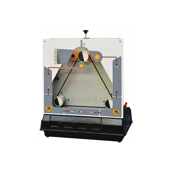
Coupled Drives Apparatus
Coupled Drives Apparatus (Product Code: SLE/ETC/05) is a multi-variable drive trainer used to study the control of speed and tension in belt-coupled drives in control and electrical engineering laboratories. Two electric motors are linked by a continuous flexible belt that also passes over a swinging arm, where a jockey wheel measures belt speed and tension. It is built by Jain Scientific Equipments Pvt Ltd (ScienceLab), an OEM engineering lab equipment manufacturer, at its own factory in Ambala, India.
Key Details
| Parameter | Detail |
|---|---|
| Motors | Two electric motors |
| Coupling | Continuous flexible belt |
| Measurement | Swinging arm with a jockey wheel measuring belt speed and tension |
| Manual adjustment | Manual control for the spring tension at the swinging arm |
| Basic control task | Vary the torque in the motors to regulate belt speed and tension |
| User guide topics | Speed and tension control; simultaneous control of velocity and tension; analysis of multi-variable control systems |
| Industrial examples | Magnetic tape drives, textile machines and paper mills |
| Product code | SLE/ETC/05 |
| Manufacturer | Jain Scientific Equipments Pvt Ltd (ScienceLab) — OEM |
| Country of origin | India (made in Ambala, Haryana) |
What Is the Coupled Drives Apparatus Used For?
In a coupled drive, changing either motor's torque affects belt speed and belt tension at the same time, so the two outputs interact. Students first control speed and tension separately, then attempt simultaneous control of velocity and tension, and discover why a multi-variable system needs a coordinated strategy rather than two independent loops.
Adjusting the spring tension at the swinging arm changes the plant, giving instructors a simple way to test how robust a controller is. The same problems occur in magnetic tape drives, textile machines and paper mills, which helps mechanical and electrical students connect theory to industry — a useful addition to any technical educational equipment list.
OEM Manufacturer
The Coupled Drives Apparatus is an OEM product of Jain Scientific Equipments Private Limited, which trades as ScienceLab. It is manufactured at the company's own licensed factory at Saha, Ambala, Haryana, India and dispatched from there to universities, colleges, dealers and importers. If you later need matching units or a replacement part such as a belt, ask us directly — you will be speaking with the maker. The ScienceLab company profile gives further background.
Related Control & Process Engineering Trainers
Drive and motion trainers from the same range that pair well with the Coupled Drives Apparatus:
- Servo Trainer — single-shaft d.c. servo speed and position control
- Engine Speed Control Apparatus — speed regulation of a loaded, non-linear machine
- Ball and Hoop Apparatus — servo position and velocity control with a moving ball
- Controller — analogue controller blocks for building speed and tension loops
All related apparatus is listed under Control & Process Engineering Trainers.
Frequently Asked Questions
What does the jockey wheel do on the Coupled Drives Apparatus?
On the Coupled Drives Apparatus, the belt passes over a swinging arm carrying a jockey wheel. The jockey wheel measures belt speed and tension, giving students the two outputs they must control at the same time.
How many motors does the Coupled Drives Apparatus have?
The Coupled Drives Apparatus has two electric motors coupled by a continuous flexible belt. Varying the torque in the motors regulates belt speed and tension, which is the basic control problem of the apparatus.
Can the belt tension on the Coupled Drives Apparatus be changed manually?
Yes. The Coupled Drives Apparatus has a manual control that adjusts the spring tension at the swinging arm, letting users change operating conditions and test how well their speed and tension controllers cope.
Which industries use drives like the Coupled Drives Apparatus?
Coupled drives like those modelled by the Coupled Drives Apparatus are used in magnetic tape drives, textile machines and paper mills, where material must move at a controlled speed while its tension is held within limits.
Who manufactures the Coupled Drives Apparatus?
Jain Scientific Equipments Pvt Ltd (ScienceLab) is the OEM manufacturer of the Coupled Drives Apparatus, producing it at its own licensed factory in Saha, Ambala, Haryana, India. Enquiries about a replacement belt or other parts go straight to the manufacturer.
Is there a user guide for the Coupled Drives Apparatus?
The Coupled Drives Apparatus description refers to a user guide covering speed and tension control, simultaneous control of velocity and tension, and analysis of multi-variable control systems. Confirm the documentation format you need when requesting a quotation.
Request a Quote
For a Coupled Drives Apparatus quotation, write to us via the contact page or add the item to the enquiry cart. The quote comes direct from the manufacturer, ScienceLab, for India and international markets.
Last updated: 24 September 2026