- Physics Lab Equipment
- Chemistry Lab Equipment
- Biology Lab Equipment
- Anatomical Lab Equipment
- Learning
- Educational Lab Equipment
- Magnets
- Agriculture
- Astronomy
- Earth Science
- Geography Lab Equipment
- Safety Lab Coat
- Laboratory
- Meteorological
- Electricity & Magnetism
- Heat
- School Lab Equipment
- Lab Glassware
- Science Lab Equipment
- Tvet Lab Equipment
- Robotics Kits Supplier and Manufacturer for Schools India
- Math Lab Equipment Manufacturers and Exporters in Ambala
- STEM Kits Manufacturers and Supplier India
- Engineering Lab Equipment
- Hospital Lab Equipment
- Water, Sanitation & Hygiene Supplies
- Cold Chain, Solar & Communication Equipment
- Nutrition
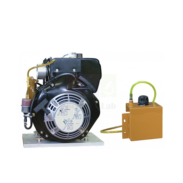
4 Stroke Diesel Engine
This compression-ignition engine is prepared for the engineering laboratory. It runs on a dynamometer test set for performance tests, and its cylinder head and crank are modified to take a cylinder head pressure transducer and a crank angle encoder. With those connected to an engine cycle analyser, the same engine moves on to in-cylinder combustion studies.
4 stroke diesel test engine details
| Parameter | Detail |
|---|---|
| Engine type | Four-stroke diesel engine for laboratory testing |
| Modifications | Modified cylinder head and crank |
| Instrumentation provision | Takes the Cylinder Head Pressure Transducer and the Crank Angle Encoder |
| Extended experiments | Transducer and encoder connect to the Engine Cycle Analyser |
| Mounting | Precision bed plate with dowels and slots that align and locate it on the dynamometer test set |
| Engine changeover | Located bed plate keeps the time to swap one engine for another short |
| Product code | SLE/EE/04 |
| Minimum order | 10 units |
| Dispatch | Usually within 7 to 10 working days |
| Manufacturer | ScienceLab (Jain Scientific Equipments Pvt Ltd), Ambala, India |
Diesel engine experiments on the test set
Load test. Locate the engine on the dynamometer test set by its bed plate dowels and run it at a steady speed. Add load in steps, and at each step record torque, speed and the time taken to use a fixed volume in the manual volumetric fuel gauge. Plot brake specific fuel consumption and brake thermal efficiency against brake power.
Combustion analysis. Fit the pressure transducer and crank angle encoder, connect them to the engine cycle analyser and record pressure against crank angle at light and at heavy load. Read off ignition delay and peak pressure, convert the trace to a pressure-volume loop and compare indicated power with brake power.
Before the first run. Use the section model of a four-stroke diesel engine to show the injector, piston crown and valve timing, and the inline injection pump trainer to explain how fuel is metered and timed. Students then know which events the pressure trace is recording.
Diesel against petrol. Swap in the 4 stroke petrol engine on the same test set and repeat the load test at matching speeds. Compare fuel used per unit of brake power and the part-load efficiency of the two ignition types.
Frequently Asked Questions About the 4 Stroke Diesel Engine
Why does this engine have a modified cylinder head and crank?
A pressure transducer needs its own passage into the combustion chamber, normally placed clear of the injector and valves. The crank needs a mounting point so an encoder can mark the exact angle of every pressure sample. Both changes are already done, so the lab does not have to machine the engine.
What stages of diesel combustion can students see on the pressure trace?
After injection starts there is a short ignition delay with little pressure change. Fuel that mixed with air during the delay then burns quickly, giving a steep rise near top dead centre. The rest burns more slowly as it mixes, and a tail of late burning follows during expansion.
What causes diesel knock, and how does it show up in the data?
Knock comes from a long ignition delay. More fuel collects before it lights, then burns almost at once, so pressure climbs very steeply. On the analyser this appears as a sharp rate of pressure rise just after ignition. A cold engine and a light load usually lengthen the delay.
How is indicated power worked out from the cycle data?
Plot pressure against cylinder volume and measure the loop area, which is the indicated work per cycle. Dividing by swept volume gives indicated mean effective pressure. A four-stroke cylinder fires once every two revolutions, so multiply the work by firing strokes per second. Indicated power minus brake power gives friction power.
Which tests can be run before the combustion instruments are fitted?
The basic load test needs only the dynamometer test set and a fuel gauge. Students find brake power from torque and speed, then brake specific fuel consumption and brake thermal efficiency from the timed fuel flow. Brake mean effective pressure follows from torque and swept volume.
Test set companions and diesel trainers
- Manual Volumetric Fuel Gauge
- Exhaust Gas Calori meter
- 4 Stroke Petrol Engine
- Section Model Of Four-Stroke Diesel Engine
- Diesel Fuel Injection System Inline Pump
- Diesel Fuel Injection System VE pump
To request a quotation, send the product name, code and quantity through our contact page or add the item to your enquiry cart.
Last updated: 20 November 2026