- Physics Lab Equipment
- Chemistry Lab Equipment
- Biology Lab Equipment
- Anatomical Lab Equipment
- Learning
- Educational Lab Equipment
- Magnets
- Agriculture
- Astronomy
- Earth Science
- Geography Lab Equipment
- Safety Lab Coat
- Laboratory
- Meteorological
- Electricity & Magnetism
- Heat
- School Lab Equipment
- Lab Glassware
- Science Lab Equipment
- Tvet Lab Equipment
- Robotics Kits Supplier and Manufacturer for Schools India
- Math Lab Equipment Manufacturers and Exporters in Ambala
- STEM Kits Manufacturers and Supplier India
- Engineering Lab Equipment
- Hospital Lab Equipment
- Water, Sanitation & Hygiene Supplies
- Cold Chain, Solar & Communication Equipment
- Nutrition
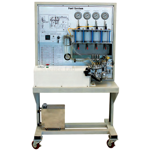
Diesel Fuel Injection System Inline Pump
The Diesel Fuel Injection System Inline Pump is a bench on which a single-phase ½ HP motor, set by an inverter, drives an inline diesel injection pump so that learners can measure injection at different RPM. Four fuel pressure gauges and a timer let them compare pressure, delivered quantity and injection pattern from one speed to the next, and check the condition of the pump and injectors.
Inline pump injection bench specifications
| Parameter | Detail |
|---|---|
| Pump type | Inline injection pump |
| Drive motor | Single-phase ½ HP |
| Speed control | Inverter |
| Instrumentation | 4 fuel pressure gauges; timer |
| Operation | Pump driven by the motor; fuel injection measured according to RPM |
| Training contents | Pump status check, motor operation, injection against RPM, injector status, fuel flux and injection patterns |
| Weight | Approx. 100 kg |
| Size | Approx. 600 × 400 × 1,200 mm |
| Product code | SLE/ATE/04 |
| Minimum order | 10 units |
| Dispatch | Usually within 7 to 10 working days |
| Manufacturer | ScienceLab (Jain Scientific Equipments Pvt Ltd), Ambala, India |
Measurements on the inline pump bench
Delivery against speed. Set the inverter to a low speed, start the timer and collect the fuel delivered during the run in a 100 ml measuring cylinder. Repeat at several higher speeds and plot delivery per run against RPM.
Reading the pressure gauges. During each run, students log all four fuel pressure gauges and relate the readings to pump speed and delivered quantity. They then discuss what a reading that falls at one speed would mean for injection at the nozzles.
Spray pattern and injector status. Watch the injection pattern at each speed and sort the sprays into fine atomisation, streaky jets and dribble after cut-off. Then link a poor pattern to the symptoms trainees meet on a running engine on the diesel engine fault diagnosis trainer.
Inline pump against common rail. Close the module on the CRDI system, where pressure is held in a rail rather than raised separately for each injection, and list the jobs the inline pump camshaft and helix no longer do.
Frequently Asked Questions About the Diesel Fuel Injection System Inline Pump
How do the plunger and helix in an inline pump control the fuel quantity?
Each pumping element has a plunger with a helical groove, turned by a control sleeve that is geared to the control rack. The plunger always makes the same stroke, but turning it changes when the helix uncovers the spill port. That changes the effective stroke and so the fuel delivered per injection.
Why must each barrel and plunger stay together as a pair?
They are lapped together to a very fine clearance, so a plunger from another barrel will leak or seize. During an overhaul, keep every pair together, lay the parts out in order in a clean workshop tray and handle the plunger by its end, not its working surface.
What does the valve above each pumping element do?
That is the delivery valve. It opens when element pressure rises and lets fuel into the injector line. When delivery ends, it closes sharply and draws back a small volume of fuel. This drops line pressure quickly, so the injector needle snaps shut without dribbling, while enough pressure remains in the line for the next injection.
How does the governor on an inline pump control speed?
Flyweights on the pump camshaft swing outwards as speed rises and act through levers on the control rack. At high speed they pull the rack towards less fuel to limit maximum speed. At idle they hold the rack where the engine runs steadily without stalling.
Why is pump output checked at several speeds after an overhaul?
A rebuilt pump must deliver the quantity its settings call for at each test speed and rack position, and every element must deliver the same amount. Uneven or wrong delivery causes rough running, smoke or low power. Measuring injection against RPM on this bench teaches that routine.
What is injection delay?
Fuel needs a short time to raise pressure in the line before the injector opens, so injection starts slightly after the pump element begins to deliver. The delay is roughly fixed in time, so it covers more crank angle as speed rises. That is one reason why injection timing is advanced at higher speeds.
Diesel fuel system and engine trainers
- Diesel Fuel Injection System VE pump
- CRDI (Common Rail Direct Injector) System
- CRDI Diesel Engine SANTAFE D Engine, Stand
- Diesel Engine Fault Diagnosis Training Equipment Auto Fault
- 4 Stroke Diesel Engine
To request a quotation, send the product name, code and quantity through our contact page or add the item to your enquiry cart.
Last updated: 14 November 2026