- Physics Lab Equipment
- Chemistry Lab Equipment
- Biology Lab Equipment
- Anatomical Lab Equipment
- Learning
- Educational Lab Equipment
- Magnets
- Agriculture
- Astronomy
- Earth Science
- Geography Lab Equipment
- Safety Lab Coat
- Laboratory
- Meteorological
- Electricity & Magnetism
- Heat
- School Lab Equipment
- Lab Glassware
- Science Lab Equipment
- Tvet Lab Equipment
- Robotics Kits Supplier and Manufacturer for Schools India
- Math Lab Equipment Manufacturers and Exporters in Ambala
- STEM Kits Manufacturers and Supplier India
- Engineering Lab Equipment
- Hospital Lab Equipment
- Water, Sanitation & Hygiene Supplies
- Cold Chain, Solar & Communication Equipment
- Nutrition
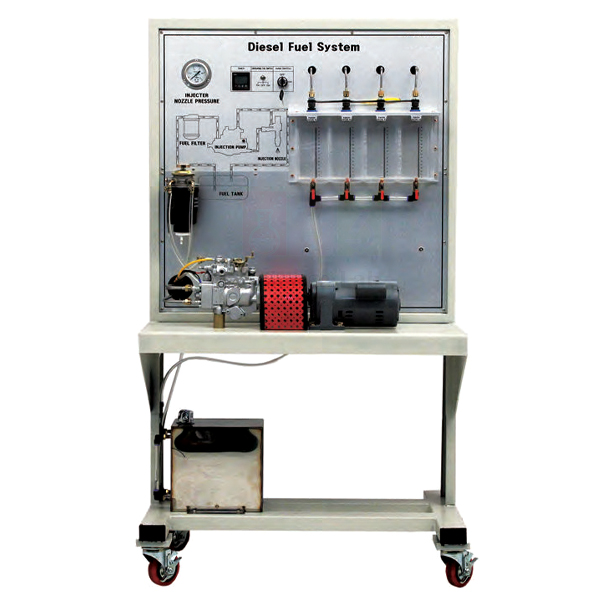
Diesel Fuel Injection System VE pump
The Diesel Fuel Injection System VE pump is a bench for measuring fuel injection against pump speed. A single-phase ½ HP motor turns the VE pump, a distributor-type rotary injection pump, and a timer sets the length of each test run. A group can then compare the fuel injected at several speeds, measure oil flow and check the condition of the pump and injectors.
VE pump injection bench specifications
| Parameter | Detail |
|---|---|
| Injection pump | VE pump (distributor-type rotary pump) |
| Drive | Single-phase ½ HP motor |
| Speed control | Provided, so the pump can be run at different speeds |
| Timing | Timer for timed test runs |
| Function | Pump driven by the motor; fuel injection measured according to RPM |
| Training contents | Pump condition check, drive motor operation, oil flow measurement, injection against RPM, injector condition, study of VE pump injection |
| Weight | Approx. 100 kg |
| Size | Approx. 600 × 400 × 1,200 mm |
| Product code | SLE/ATE/03 |
| Minimum order | 10 units |
| Dispatch | Usually within 7 to 10 working days |
| Manufacturer | ScienceLab (Jain Scientific Equipments Pvt Ltd), Ambala, India |
Practicals on the VE pump bench
Injection curve. Run the motor at a chosen speed, start the timer and catch the injected fuel in a polypropylene measuring cylinder. Repeat over several speeds with the same run time and plot quantity against RPM. Then explain the shape of the curve from how the control collar and governor of a VE pump meter the fuel.
Oil flow and injector condition. Measure the oil flow over a timed run and record it with the speed. Then check each injector for spray shape, a clean cut-off at the end of injection and any dribble or leakage at the nozzle, and write the pump and injector results on one sheet.
Distributor pump against inline pump. Run the same speed steps on the inline pump bench. Students compare one distributor plunger serving every outlet in turn with a separate element for each cylinder, and list the parts each design needs.
Where the fuel goes. On the section model of four-stroke diesel engine, students trace fuel from the injection pump to the injector and see where the spray enters the pre-chamber near the end of compression.
Frequently Asked Questions About the Diesel Fuel Injection System VE pump
How does one plunger serve every cylinder in a VE pump?
A vane feed pump fills the pump housing with fuel. A single plunger, driven by a cam plate riding on rollers, turns and moves back and forth at the same time. Each forward stroke builds injection pressure while the distributor slot in the plunger lines up with one outlet, so the cylinders are served in turn.
What sets the amount of fuel per injection in a VE pump?
A control collar slides along the plunger. Injection ends when the collar uncovers the spill port in the plunger and the pressure escapes into the pump housing. The governor moves the collar with accelerator position and speed: moving it one way lengthens the effective stroke and gives more fuel.
Why might an engine with a VE pump keep running after the key is turned off?
The pump has an electric shut-off solenoid that opens the fuel inlet when the key is on and closes it when the key is off. If the solenoid sticks open, or dirt or varnish holds its plunger, fuel keeps flowing. Check the solenoid feed and listen for its click before blaming the pump.
How does a VE pump advance injection timing as speed rises?
Fuel pressure inside the pump housing rises with speed. It pushes an advance piston that turns the roller ring slightly against the direction of cam plate rotation, so each injection starts earlier. If the advance piston seizes, timing stays fixed and the engine may smoke, lose power or start badly.
Why does fuel cleanliness matter so much to a VE pump?
Diesel fuel itself lubricates the pump. Water or dirt wears the cam plate, rollers and plunger, and can seize the rotor in its head. Metal fragments from that wear then travel on to the injectors. Protect the pump with a sound filter, a regularly drained water trap and clean fuel.
Why may a VE pump start poorly after the fuel system has been opened?
Air left in the filter or lines stops the pump building pressure. Bleed the system as the service data describes, check that suction-side unions are tight so no air is drawn in, and make sure the shut-off solenoid is powered before cranking again.
Diesel injection and engine trainers
- Diesel Fuel Injection System Inline Pump
- CRDI (Common Rail Direct Injector) System
- CRDI Diesel Engine Stand, Motor Type
- Diesel Engine Fault Diagnosis Training Equipment Auto Fault
- Section Model Of Four-Stroke Diesel Engine
To request a quotation, send the product name, code and quantity through our contact page or add the item to your enquiry cart.
Last updated: 15 November 2026