- Physics Lab Equipment
- Chemistry Lab Equipment
- Biology Lab Equipment
- Anatomical Lab Equipment
- Learning
- Educational Lab Equipment
- Magnets
- Agriculture
- Astronomy
- Earth Science
- Geography Lab Equipment
- Safety Lab Coat
- Laboratory
- Meteorological
- Electricity & Magnetism
- Heat
- School Lab Equipment
- Lab Glassware
- Science Lab Equipment
- Tvet Lab Equipment
- Robotics Kits Supplier and Manufacturer for Schools India
- Math Lab Equipment Manufacturers and Exporters in Ambala
- STEM Kits Manufacturers and Supplier India
- Engineering Lab Equipment
- Hospital Lab Equipment
- Water, Sanitation & Hygiene Supplies
- Cold Chain, Solar & Communication Equipment
- Nutrition

Differential Gear
The Differential Gear is a hand-turned cut-section trainer built around a real axle differential, so students can watch how the drive from the pinion is shared between the two axle shafts. The incised sections are painted in different colours, which lets each gear in the power path be picked out, named and followed as the assembly turns.
Differential gear trainer specifications
| Parameter | Detail |
|---|---|
| Composition | Differential gear from a real axle |
| Operation | Manual; gear movement observed by turning by hand |
| Construction | Teaching unit with incised (cut-away) sections |
| Colour coding | Incised sections painted in different colours |
| Weight | Approx. 40 kg |
| Size | Approx. 800 × 500 × 300 mm |
| Product code | SLE/ATE/25 |
| Minimum order | 10 units |
| Dispatch | Usually within 7 to 10 working days |
| Manufacturer | ScienceLab (Jain Scientific Equipments Pvt Ltd), Ambala, India |
Driveline practicals with the differential
Straight ahead and cornering. Chalk a mark on each axle shaft and turn the input with both sides free: the shafts turn together and the small gears stay still on their cross-shaft. Then hold one shaft and turn the input again. The other shaft now runs at twice the speed of the carrier, and students see the small gears spinning.
Final drive ratio by counting. Count the teeth on the pinion and on the crown wheel through the cut-away, or count the input turns for one turn of the carrier. Divide to find the final drive reduction and compare the two methods.
Tracing the power path. Using the colour coding, students label each part from the input pinion to the crown wheel, carrier, small gears, side gears and axle shafts. The heavy duty vehicles differential gear model and the tractor differential gear model then show the same idea at a larger scale.
A bevel epicyclic train. Set the trainer beside the planetary gear cut model and compare the two. The differential carrier works as the planet carrier, the small gears as planets and the two side gears as the other members of the set. Students then explain why holding one side gear makes the other speed up.
Frequently Asked Questions About the Differential Gear
Why does a driven axle need a differential?
On a bend, the outer wheel travels further than the inner wheel in the same time, so it must turn faster. With both wheels fixed to one shaft, a tyre would have to scrub, wearing it and upsetting the handling. The differential lets the wheels turn at different speeds while both stay driven.
What do the small gears inside the carrier do when going straight and when cornering?
Going straight, the carrier, small gears and side gears turn together as one unit and the small gears do not spin on their shaft. On a bend, the small gears rotate on their shaft, letting one side gear speed up while the other slows by the same amount.
What is the final drive ratio?
It is the reduction between the drive pinion and the crown wheel, found by dividing the crown wheel teeth by the pinion teeth. Because the pinion is much smaller, it lowers speed and multiplies torque, and it also turns the drive through a right angle towards the wheels.
Does an open differential share torque equally, and why can one wheel spin?
It sends equal torque to both sides, but that torque is limited by the wheel with less grip. If one wheel is on mud or ice, it spins freely and the other wheel gets just as little torque, so the vehicle may not move. Limited-slip and locking differentials are made to overcome this.
Which noises point to a worn differential?
A whine or hum that rises and falls with road speed suggests worn or badly set crown wheel and pinion teeth or bearings. A clunk when the throttle is applied or released points to too much backlash. Grinding or binding during slow, tight turns often comes from the small gears or side gears.
How can differential noise be told apart from wheel bearing noise?
Differential noise usually changes between accelerating and coasting, because the load on the gear teeth changes. Wheel bearing noise tends to change when the vehicle sways left or right on a bend, as weight shifts onto one bearing. A drive shaft joint often clicks on full-lock turns.
Axle, gearbox and transmission trainers
- Heavy Duty Vehicles Differential Gear Model
- Tractor Differential Gear Model
- Vehicle Transmission 5 Speed Manual Gearbox
- FF Auto Transmission Stand Type
- Cut Model Of Planetary Gear System
- Cut Model Of Automatic Transmission System
To request a quotation, send the product name, code and quantity through our contact page or add the item to your enquiry cart.
Last updated: 14 November 2026

Heavy Duty Vehicles Differential Gear Model
The Heavy Duty Vehicles Differential Gear Model opens up a large heavy machinery differential so that trainees can see parts that stay hidden on a working axle, including the planetary gear on the wheel. Each component is painted a different colour, and the assembly of about 150 kg stands on a steel frame with 5-inch lockable wheels.
Heavy duty differential model specifications
| Parameter | Detail |
|---|---|
| Composition | Large heavy machinery differential gear |
| Visibility | Parts not visible on an actual unit are opened up; the planetary gear can be seen directly on the wheel |
| Colour coding | Each component coloured differently for teaching |
| Stand | Steel frame with 5-inch lockable wheels |
| Weight | Approx. 150 kg |
| Size | Approx. 2,000 × 800 × 500 mm |
| Training focus | Component identification, operating state, inspection and troubleshooting |
| Product code | SLE/ATE/26 |
| Minimum order | 10 units |
| Dispatch | Usually within 7 to 10 working days |
| Manufacturer | ScienceLab (Jain Scientific Equipments Pvt Ltd), Ambala, India |
Heavy axle lessons on the differential model
Following the drive to the wheel. Starting at the input, trainees trace the drive through the differential and out along the axle to the planetary set on the wheel. At the wheel they name the member that is driven, the member that is held and the member that turns the hub, then explain why the reduction sits so close to the tyre.
Inspection walk-round. The instructor names a symptom, such as noise, uneven drive or one wheel end running hot. Trainees find the coloured components that could cause it, describe each one in its normal operating state, and set out the order in which a mechanic would inspect them.
From a small differential to a heavy axle. Begin with the hand-turned differential gear to show the basic principle, then move to this model to show how heavy machines add a wheel-end reduction. The cut model of planetary gear system lets students compare the sun, planet and ring layout used inside an automatic gearbox.
Farm and heavy machine comparison. Set the tractor differential gear model beside this one and compare where each machine takes its final reduction. An assessment can end with each trainee naming the parts against the colour code without notes.
Frequently Asked Questions About the Heavy Duty Vehicles Differential Gear Model
Which member of the wheel-end planetary set takes the drive?
In the usual heavy-duty layout, the axle shaft turns the sun gear in the centre. The ring gear is held to the axle housing, so the planet gears roll around inside it and carry the planet carrier with them, which turns the wheel hub. Holding the ring gear gives a speed reduction and a matching rise in torque.
Why do heavy machines add a reduction at the wheel as well as in the differential?
Torque is multiplied at the last stage, close to the tyre. The differential and axle shafts then carry less torque and can be lighter than they would need to be if all the reduction sat in the centre of the axle. The machine still gets the high wheel torque it needs for pulling and climbing.
What does a differential lock do, and when is it used?
An open differential gives each side the same torque, so a wheel on mud limits the drive available to the wheel with grip. A lock joins both sides so they turn together and the wheel with grip can take more torque. It is engaged at low speed on poor ground and released before turning on firm ground. No lock is listed for this model.
Why might one wheel end run hot on a heavy machine?
Common causes are low gear oil or the wrong grade, worn bearings, and a brake that does not fully release and drags. Check the oil level at the wheel end first with the machine on level ground. After a run, compare the two hubs for heat, then inspect the bearings and brake on the hotter side.
What does an oil leak at the wheel hub lead to?
A leaking seal lets gear oil out and dirt in, so the planet gears and bearings run short of oil and wear quickly. Oil that reaches the brakes also weakens braking. Replace a weeping seal early, clean the area and refill to the correct level with the grade given in the machine service manual.
How should the model be set up for a class?
Roll it on a level floor and lock the 5-inch wheels before anyone leans on the frame. At about 150 kg it needs two people to move it. Leave clear space along both long sides of its 2,000 mm length so the group can walk round and point out each coloured part.
Driveline, axle and heavy vehicle trainers
- Differential Gear
- Tractor Differential Gear Model
- Cut Model Of Planetary Gear System
- Vehicle Transmission 5 Speed Manual Gearbox
- Trailer Air Brake Training Equipment
- CRDI Diesel Engine Power Train System F/R Type
To request a quotation, send the product name, code and quantity through our contact page or add the item to your enquiry cart.
Last updated: 14 November 2026

Suspension Cable Demonstration
Suspension Cable Demonstration (Product Code: SLE/ESA/01) is a magnetic engineering science kit used to study the shape and tension of a suspension cable in structures and applied mechanics classes, fitted to the Work Panel (STF1). A roller chain acts as the cable, held on magnetically mounted sprocket pulleys, while spring balances read the cable tension under hanging weights. It is made by Jain Scientific Equipments Pvt Ltd (ScienceLab), an OEM manufacturer, at its own factory in Ambala, India.
Key Details
| Parameter | Detail |
|---|---|
| Mounting | For use with the Work Panel (STF1); magnetic parts fit to the panel |
| Cable | Roller chain |
| Cable supports | Magnetically mounted sprocket pulleys |
| Tension measurement | Spring balances |
| Loading | Set of weight hangers and weights |
| Configurations | Symmetrical and non-symmetrical cables; point loads or evenly-spread loads |
| Theory covered | Suspension cable compared with a catenary cable; catenary and parabolic theory |
| Documentation | Fully illustrated User Guide with theory, experiments and typical results |
| Product code | SLE/ESA/01 |
| Manufacturer | Jain Scientific Equipments Pvt Ltd (ScienceLab) — OEM |
| Country of origin | India (made in Ambala, Haryana) |
What Is the Suspension Cable Demonstration Used For?
A cable hanging under its own weight takes the shape of a catenary, but when it carries a load spread evenly along the horizontal, as the deck of a suspension bridge does, its shape approaches a parabola. With this kit, students hang the roller chain between the sprocket pulleys on the Work Panel, let it sag freely, then add weight hangers at intervals to create an evenly-spread load. Measuring the sag and the spring balance tensions in each case shows which theory fits better.
The same parts can be rearranged into non-symmetrical cable arrangements or loaded at single points, so one kit carries a class from introductory statics to more advanced structures work. Because every part mounts magnetically, set-ups change quickly within a lesson and can be repeated for each student group. The illustrated User Guide supplies theory and typical results for comparison, making the kit useful engineering lab equipment in India for civil engineering and technician courses.
What to Specify When Ordering
- Whether you already have the Work Panel (STF1) the kit mounts on, or need a panel as well
- Number of kits, for example one per panel or student group
- Delivery location in India or abroad
OEM Manufacturer
ScienceLab is the OEM for the Suspension Cable Demonstration kit. Jain Scientific Equipments Private Limited, which trades as ScienceLab, manufactures it at its own licensed factory at Saha, Ambala, Haryana, India, and supplies it factory-direct to engineering colleges, polytechnics, dealers and importers.
Because the maker answers every enquiry, compatibility with your work panel and repeat orders for extra kits can be confirmed with us before you buy. The ScienceLab company profile has more about the company.
Related Laboratory Equipment
The panel this kit mounts on, plus other structures and statics apparatus:
- Engineering Science Work Panel — the perforated metal panel that engineering science kits are fitted to.
- Simple Suspension Bridge — suspension bridge behaviour on a separate model.
- Equilibrium Of Rigid Body — forces on an inclined ladder structure.
- Equilibrium Of A Force — for experiments on the equilibrium of forces.
Browse Structures & Statics Lab Equipment for more structures teaching equipment.
Frequently Asked Questions
What do I need to use the Suspension Cable Demonstration?
The Suspension Cable Demonstration is designed for use with the Work Panel (STF1), and its magnetic parts fit onto that panel. Our Engineering Science Work Panel is listed separately; confirm the panel with us when you request a quote.
What is included in the Suspension Cable Demonstration?
The Suspension Cable Demonstration includes a roller chain that acts as the cable, magnetically mounted sprocket pulleys, and a set of weight hangers and weights, with a fully illustrated User Guide. Spring balances are used in the kit to measure cable tension.
What theory does the Suspension Cable Demonstration cover?
The Suspension Cable Demonstration compares a suspension cable with a catenary cable and analyses the results using catenary and parabolic theory, so students see when each model describes the measured cable shape and tension.
Which load cases can be set up with the Suspension Cable Demonstration?
The Suspension Cable Demonstration can form symmetrical and non-symmetrical cables, loaded either with point loads or with evenly-spread loads, giving several experiments from one set of magnetic parts.
Who manufactures the Suspension Cable Demonstration?
The Suspension Cable Demonstration is manufactured by Jain Scientific Equipments Pvt Ltd (ScienceLab), the OEM, at its own licensed factory at Saha, Ambala, Haryana, India. Enquiries and quotations are handled directly by the manufacturer.
Can the Suspension Cable Demonstration be ordered for a full class?
Yes, the Suspension Cable Demonstration can be quoted in multiple kits for institutions and dealers in India and international markets. State the number of kits and whether work panels are needed through the contact page.
Request a Quote
For a quotation on the Suspension Cable Demonstration (SLE/ESA/01), contact us through the contact page or add it to the enquiry cart. Your quote comes straight from the manufacturer.
Last updated: 24 September 2026

Tractor Differential Gear Model
In the Tractor Differential Gear Model, a single phase 220V, 180W geared motor turns a set of tractor shafts so that trainees can watch the differential, axle and reduction gears drive the wheels. A speed control slows the drive for close study, and parts that stay hidden on a real tractor are opened up and painted in different colours.
Tractor differential model specifications
| Parameter | Detail |
|---|---|
| Drive motor | Single phase 220V, 180W, with mounted reduction gear |
| Composition | Tractor shafts, power switch, power lamp, emergency switch, fuse holder and speed control |
| Systems shown | Differentials, axle, reduction gears and wheel operation |
| Construction | Parts not seen on an actual tractor opened for viewing; each component coloured differently |
| Stand | Steel frame with 5-inch lockable wheels |
| Weight | Approx. 150 kg |
| Size | Approx. 1,500 × 800 × 800 mm |
| Product code | SLE/ATE/27 |
| Minimum order | 10 units |
| Dispatch | Usually within 7 to 10 working days |
| Manufacturer | ScienceLab (Jain Scientific Equipments Pvt Ltd), Ambala, India |
Tractor driveline practicals on the motor-driven model
Pre-start check. Before each session, a trainee locks the wheels of the steel frame, confirms the fuse holder is fitted, turns the speed control fully down and checks that the emergency switch is within reach. Only then is the power switch turned on, with the power lamp confirming the unit is live. The rest of the group stands clear of the gears.
Counting the reduction. With the drive running slowly, chalk a mark on the input shaft and on one wheel. Trainees count input turns for one wheel turn to find the overall reduction, then count again at the shaft between the differential and the reduction gears to see how much each stage contributes.
Where the extra reduction sits. Compare the model with the hand-turned differential gear and the heavy duty vehicles differential gear model. Trainees note that a car-type axle has one reduction at the crown wheel, while tractor and heavy machine axles add a further stage, and they explain why that stage is placed after the differential.
From engine to wheel. Finish by following the drive through the whole tractor: the clutch structure trainer shows how the engine is connected and disconnected, and the large yard tractor engine fault diagnosis system covers the engine side. Trainees then draw the complete power path from the engine to the rear wheels.
Frequently Asked Questions About the Tractor Differential Gear Model
What does the final drive do on a tractor?
The final drive is the last gear reduction between the differential and the rear wheels. It lowers wheel speed and raises torque once more, giving the slow, strong pull needed for ploughing and hauling. Placing it after the differential means the differential and the half shafts carry less torque, so they can be lighter.
Which parts make up a tractor differential, and how does the drive pass through them?
A bevel pinion on the drive shaft turns the crown wheel, which is bolted to the differential case. The case carries small pinions on a cross pin, and these mesh with two side gears splined to the half shafts. The case drives both side gears, and the small pinions let them run at different speeds on turns.
How is the rear axle oil on a tractor checked?
Park the tractor on level ground, let the oil settle and check it at the level plug or dipstick that the operator's manual shows. On many tractors the gearbox and rear axle share one oil. Milky or grey oil means water has got in through condensation or worn seals, so drain it and refill with fresh oil.
How can trainees check a tractor rear axle for worn bearings?
With the axle raised and safely supported, rock the wheel at the top and bottom to feel for play, then turn it slowly and listen for roughness. A growl that rises with travel speed also points to bearing wear. Metal particles on the drain plug confirm that something inside is wearing.
Why run the model at low speed during a lesson?
At low speed trainees can follow each gear by eye, count shaft turns and see the speed fall at every reduction stage. It also gives more time to react. Keep hands, sleeves and pointers away from the open gears, and use the emergency switch at once if anything catches.
Tractor and driveline trainers for a mechanic lab
- Differential Gear
- Heavy Duty Vehicles Differential Gear Model
- Large Yard Tractor Engine Fault Diagnosis System
- Clutch Structure Trainer Mechanical Manual
- Vehicle Transmission 5 Speed Manual Gearbox
To request a quotation, send the product name, code and quantity through our contact page or add the item to your enquiry cart.
Last updated: 14 November 2026

Equilibrium Of Rigid Body
Equilibrium Of Rigid Body (Product Code: SLE/ESA/02) is a magnetic work panel kit used to study the forces acting on an inclined ladder, a classic rigid-body equilibrium problem, in applied mechanics and engineering science classes. A model ladder is held at angles between 15 and 45 degrees, with or without a climbing mass at any position along its length, while the horizontal and vertical forces are measured. It is made by Jain Scientific Equipments Pvt Ltd (ScienceLab), an OEM manufacturer, at its own factory in Ambala, India.
Key Details
| Parameter | Detail |
|---|---|
| Mounting | For use with the Work Panel; magnetic parts fit to the panel |
| Rigid body | Model ladder structure |
| Ladder angle | Adjustable, 15 to 45 degrees |
| Climbing mass | Used with or without, at any position along the ladder |
| Forces measured | Horizontal and vertical forces |
| Documentation | Fully illustrated user guide with theory, experiments and typical results |
| Product code | SLE/ESA/02 |
| Manufacturer | Jain Scientific Equipments Pvt Ltd (ScienceLab) — OEM |
| Country of origin | India (made in Ambala, Haryana) |
What Is the Equilibrium of Rigid Body Kit Used For?
A ladder leaning against a wall is the textbook example of a rigid body in equilibrium: its weight, any load on it and the reactions at the top and foot must balance horizontally, vertically and in moments. With this kit fixed to the Work Panel, students set the ladder angle, read the horizontal and vertical forces, and compare them with the values predicted by the equilibrium equations.
Moving the climbing mass up the ladder step by step shows how the horizontal force at the foot grows, which explains why a real ladder is most likely to slip when someone is near the top. Repeating the series at several angles between 15 and 45 degrees shows how the ladder angle changes the forces. With theory and typical results in the illustrated user guide, the kit fits well into engineering lab equipment programmes at polytechnics and colleges in India.
OEM Manufacturer
ScienceLab is the OEM behind this kit. Jain Scientific Equipments Private Limited (CIN U29309HR2020PTC087597), which trades as ScienceLab, manufactures it at its licensed factory at 449, HSIIDC Industrial Area, Saha, Ambala, Haryana (Factory Licence AMB-ONLINE-CHD-J-414).
Colleges, training institutes, dealers and importers buy it directly from that factory, and questions about work panel compatibility or extra kits for more student groups go straight to the manufacturer. Read more on the ScienceLab company profile.
Related Laboratory Equipment
The mounting panel and other statics experiments that follow on from the ladder problem:
- Engineering Science Work Panel — the perforated metal panel that engineering science kits are fitted to.
- Equilibrium Of A Beam — moments and reaction forces on a rigid beam.
- Friction Slide Apparatus — friction, the factor that decides when a real ladder slips.
- Suspension Cable Demonstration — cable shapes and tensions studied on a work panel.
More structures apparatus is listed under Structures & Statics Lab Equipment.
Frequently Asked Questions
What does the Equilibrium Of Rigid Body kit demonstrate?
The Equilibrium Of Rigid Body kit demonstrates the forces around an inclined ladder-type structure, letting students compare measured horizontal and vertical forces with the conditions for equilibrium of a rigid body.
What ladder angles can be set on the Equilibrium Of Rigid Body kit?
On the Equilibrium Of Rigid Body kit, the model ladder angle can be adjusted between 15 and 45 degrees, and each angle can be tested with or without the climbing mass at any position along the ladder.
What else is needed to use the Equilibrium Of Rigid Body kit?
The Equilibrium Of Rigid Body kit is designed for use with the Work Panel, because its magnetic parts fit onto that panel. Our Engineering Science Work Panel is listed separately; confirm the panel when you request a quote.
How are forces read on the Equilibrium Of Rigid Body kit?
The Equilibrium Of Rigid Body kit measures the horizontal and vertical forces on the ladder for each angle and mass position. The measuring parts included are not detailed in the listing, so ask through the contact page and the quotation will state them.
Does the Equilibrium Of Rigid Body kit include a user guide?
Yes. Each Equilibrium Of Rigid Body kit is supplied with a fully illustrated user guide containing theory, experiments and typical results, which helps staff prepare lessons and lets students check their readings.
Who manufactures the Equilibrium Of Rigid Body kit?
The Equilibrium Of Rigid Body kit is manufactured by Jain Scientific Equipments Pvt Ltd (ScienceLab), the OEM, at its own licensed factory at Saha, Ambala, Haryana, India. Quotations for India and international markets come directly from the manufacturer.
Request a Quote
Request a price for the Equilibrium Of Rigid Body kit (SLE/ESA/02) via the contact page or add it to the enquiry cart, noting whether you also need a work panel. The manufacturer prepares the quotation directly.
Last updated: 24 September 2026

Equilibrium Of A Beam
Equilibrium Of A Beam (Product Code: SLE/ESA/03) is a magnetic work panel kit used to study forces, moments and reaction forces on a rigid beam at equilibrium in engineering science and applied mechanics classes. Masses, magnetic mounts and spring balances apply and measure the forces, and the beam can be supported in several ways, including simply supported or balanced. It is made by Jain Scientific Equipments Pvt Ltd (ScienceLab), an OEM manufacturer, at its own factory in Ambala, India.
Key Details
| Parameter | Detail |
|---|---|
| Mounting | Magnetic parts fit to the Work Panel |
| Test member | Rigid beam |
| Force application | Masses, magnetic mounts and spring balances |
| Support arrangements | Several, including simply supported or balanced |
| Measurements | Forces around the beam at equilibrium, including reaction forces |
| Theory compared | Theory of moments and equilibrium |
| Product code | SLE/ESA/03 |
| Manufacturer | Jain Scientific Equipments Pvt Ltd (ScienceLab) — OEM |
| Country of origin | India (made in Ambala, Haryana) |
What Is the Equilibrium of a Beam Kit Used For?
Before students can analyse bending in a beam, they need its support reactions, and those follow from two rules: the forces must balance, and the moments about any point must balance. With this kit on the Work Panel, they set the beam up as simply supported, hang masses at chosen positions and read the reaction forces from the spring balances. The measured values are then set against the reactions calculated by taking moments.
Rearranging the magnetic mounts turns the same beam into a balanced beam, where loads on each side must produce equal and opposite moments, a direct link to the principle of levers. Because each set-up takes only minutes on the panel, groups can test several load cases in one practical and see how closely experiment matches theory. It is straightforward engineering lab equipment for colleges, polytechnics and technical schools in India, and a natural first step before bending moment experiments.
What to Specify When Ordering
- Whether you already have the Work Panel the kit fits to, or need one as well
- Number of kits for your student groups
- Any teaching documentation you need with the kit (ask us what is supplied)
OEM Manufacturer
This beam kit is manufactured by ScienceLab as the OEM. Jain Scientific Equipments Private Limited, the company behind the ScienceLab trading name, makes it at its own licensed factory at Saha, Ambala, Haryana, India, and ships it factory-direct to engineering institutions, dealers and importers in India and international markets.
For extra masses, spare spring balances or more kits for additional panels, ask us; the manufacturer handles these requests itself. Visit the ScienceLab profile for more about the company.
Related Laboratory Equipment
The panel for this kit and the experiments that come before and after it in a statics course:
- Engineering Science Work Panel — the perforated metal panel that engineering science kits are fitted to.
- Bending Moment Apparatus — the next step: shear force and bending moment inside a loaded beam.
- Equilibrium Of Rigid Body — equilibrium of an inclined ladder structure.
- Equilibrium Of A Force — for experiments on the equilibrium of forces.
Explore General Products for more structures and mechanics kits.
Frequently Asked Questions
What does the Equilibrium Of A Beam kit demonstrate?
The Equilibrium Of A Beam kit demonstrates forces, moments and reaction forces around a rigid beam at equilibrium. Students compare the forces they measure with theoretical values found from the theory of moments and the conditions of equilibrium.
How are forces applied on the Equilibrium Of A Beam kit?
The Equilibrium Of A Beam kit uses masses, magnetic mounts and spring balances to apply forces to the rigid beam. All parts fit magnetically to the Work Panel, so load positions can be changed quickly between readings.
Which support arrangements does the Equilibrium Of A Beam kit allow?
The Equilibrium Of A Beam kit allows several ways of supporting the beam, including simply supported and balanced arrangements, so one kit covers both support-reaction problems and lever-type moment balance experiments.
What else is needed to use the Equilibrium Of A Beam kit?
The Equilibrium Of A Beam kit is designed to be fitted to the Work Panel with its magnetic parts. Our Engineering Science Work Panel is listed separately; confirm the panel with us when you request a quote.
Does the Equilibrium Of A Beam kit come with a user guide?
The listing for the Equilibrium Of A Beam kit does not mention a user guide. If you need written instructions or typical results, ask through the contact page and the quotation will state what documentation is supplied.
Who manufactures the Equilibrium Of A Beam kit?
The Equilibrium Of A Beam kit is manufactured by Jain Scientific Equipments Pvt Ltd (ScienceLab), the OEM, at its own licensed factory at Saha, Ambala, Haryana, India. Enquiries and quotations are answered by the manufacturer directly.
Request a Quote
For a price on the Equilibrium Of A Beam kit (SLE/ESA/03), send your quantity and panel requirement through the contact page, or add it to the enquiry cart. Quotations come straight from the manufacturer.
Last updated: 24 September 2026

Equilibrium Of A Force
Equilibrium Of A Force (Product Code: SLE/ESA/04) is a statics experiment kit used to study how several forces acting at different angles balance one another in engineering and physics laboratories. Mounted on a work panel, it lets students set up to five forces at any angles on a single point, or apply forces to two points. It is made by Jain Scientific Equipments Pvt Ltd (ScienceLab), an OEM manufacturer, at its own factory in Ambala, India, as part of its mechanics lab equipment range.
Specifications
| Parameter | Detail |
|---|---|
| Experiments | Forces pulling on one or more points at different angles; forces can also be applied to two points |
| Number of forces | Up to five, set at any angles |
| Force application | Masses, hooks, pulleys and cords acting on a single point |
| Kit parts | Cords, rings, magnetic mounts, magnetic protractors, pulleys, weights, hooks and a spring balance |
| Mounting | For use with the Work Panel |
| Methods introduced | Bow’s Notation and the drawing method of finding forces |
| Documentation | Fully illustrated user guide with theory, experiments and typical results, supplied with each kit |
| Product code | SLE/ESA/04 |
| Manufacturer | Jain Scientific Equipments Pvt Ltd (ScienceLab) — OEM |
| Country of origin | India (made in Ambala, Haryana) |
What Is the Equilibrium of a Force Kit Used For?
Students hang weights from cords that run over pulleys and meet at a ring, read each cord angle on the magnetic protractors, and then check the balance by drawing a triangle or polygon of forces to scale. The kit introduces Bow’s Notation, the system of lettering the spaces between forces so that each force diagram can be drawn in an orderly way.
Typical exercises start with three cords, extend to four or five forces, and use the spring balance to measure one force directly for comparison with the graphical answer. Applying forces to two points then shows how a system behaves when the loads do not all meet at one point. It suits first-year statics practicals in colleges and polytechnics that stock engineering lab equipment in India, as well as senior school physics. Tip: let the ring settle and keep cords clear of the panel before reading angles, so pulley friction does not distort the result.
What to Specify When Ordering
- Whether you already have the Work Panel or need it quoted with the kit.
- The number of kits, usually one per student group working at a panel.
- Any extra weights or a spare spring balance for additional groups.
- Other statics experiments you plan to run on the same panel, so they can be quoted together.
OEM Manufacturer
ScienceLab is the trading name of Jain Scientific Equipments Private Limited, the OEM (original equipment manufacturer) of the Equilibrium Of A Force kit. The kit is made and assembled at the company’s own licensed factory at Saha, Ambala, Haryana, India, and goes factory-direct to schools, colleges, dealers and importers in India and international markets. Replacement cords, pulleys or weights and repeat orders are handled by the manufacturer itself, so just ask us for what your lab needs. More about the company is on the ScienceLab company profile.
Related Structures & Statics Lab Equipment
These items share the same panel or carry the statics experiments on to beams and rigid bodies.
- Engineering Science Work Panel — the panel on which this kit’s magnetic mounts and protractors are set out.
- Equilibrium Of Rigid Body — the follow-on experiment with forces and moments acting on a body.
- Equilibrium Of A Beam — applies the same equilibrium conditions to a loaded beam.
- Force Table — an alternative horizontal method for resolving concurrent forces.
- Force Meter/Spring Balance — an extra balance for measuring cord tension.
Browse more statics and structures apparatus in Structures & Statics Lab Equipment.
Frequently Asked Questions
What does the Equilibrium Of A Force kit include?
The Equilibrium Of A Force kit includes cords, rings, magnetic mounts, magnetic protractors, pulleys, weights, hooks and a spring balance, together with a fully illustrated user guide covering theory, experiments and typical results. Confirm with us whether your quotation should also include the Work Panel.
How many forces can be set up with the Equilibrium Of A Force kit?
Up to five forces can be set up at any angles with the Equilibrium Of A Force kit. They can all act on a single point, or students can arrange the cords to apply forces to two points for a more advanced exercise.
Does the Equilibrium Of A Force kit need a work panel?
Yes, the Equilibrium Of A Force kit is designed for use with the Work Panel, where its magnetic mounts and magnetic protractors let pulleys and angle scales be positioned freely. If you do not already own the panel, mention this when you request a quotation.
What is Bow’s Notation in these experiments?
Bow’s Notation, introduced by the Equilibrium Of A Force kit, is a labelling method in which the spaces between forces are lettered, so each force is named by the two spaces it separates. It makes drawing the force polygon and finding unknown forces graphically far more orderly.
Who manufactures the Equilibrium Of A Force kit?
The Equilibrium Of A Force kit is manufactured by Jain Scientific Equipments Pvt Ltd (ScienceLab) as the OEM, at its own licensed factory at Saha, Ambala, Haryana, India. Quotations, repeat orders and spare parts are handled directly by the manufacturer.
Is a calibration certificate available for the spring balance?
A calibration certificate is not listed as standard for the Equilibrium Of A Force kit. If your institution needs one for the spring balance or weights, please discuss it with us through the contact page before ordering so we can confirm what is possible.
Can the Equilibrium Of A Force kit be supplied in bulk or for export?
Yes, ScienceLab manufactures the Equilibrium Of A Force kit in multi-kit quantities for institutions and dealers in India and international markets. Share the quantity, delivery destination and whether the Work Panel is needed, and we will prepare a quotation.
Request a Quote
To order the Equilibrium Of A Force kit (SLE/ESA/04), send your quantity and delivery details through the contact page or add the item to the enquiry cart. Quotations come direct from the manufacturer, Jain Scientific Equipments Pvt Ltd (ScienceLab), Ambala.
Last updated: 20 November 2026
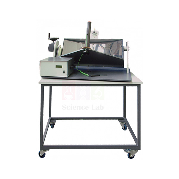
Focusing Solar Energy Collector
Focusing Solar Energy Collector (Product Code: SLE/ESA/05) is a parabolic-reflector solar concentrator on a mobile frame, used to demonstrate the principles, advantages and limits of focusing solar energy in engineering and renewable energy teaching labs. Students aim a polished stainless steel reflector at the sun and measure how hot copper collectors of four sizes become. It is made by Jain Scientific Equipments Pvt Ltd (ScienceLab), an OEM manufacturer, at its own factory in Ambala, India.
Key Details
| Parameter | Detail |
|---|---|
| Design | Focusing solar energy collector on a mobile frame, specially designed for educational use |
| Reflector | Highly polished stainless steel parabolic reflector |
| Reflector mounting | Trunnion bearings on a turntable; horizontal and vertical position adjustable |
| Energy collector | Copper cylinder with an embedded thermocouple that measures cylinder temperature |
| Collector sizes | Four different sizes supplied, for comparing concentration ratios |
| Radiation measurement | Solarimeter attached to the reflector carrier measures incident solar radiation |
| Ambient reference | Extra thermocouple measures ambient temperature |
| Collector cover | Removable transparent cover for shielded and unshielded collector studies |
| Product code | SLE/ESA/05 |
| Manufacturer | Jain Scientific Equipments Pvt Ltd (ScienceLab) — OEM |
| Country of origin | India (made in Ambala, Haryana) |
What Is the Focusing Solar Collector Used For?
Concentrating collectors reach higher temperatures than flat panels because a large reflector area focuses sunlight onto a small absorber. With this apparatus, students follow the sun by turning the reflector on its turntable and tilting it on its trunnions until the focus falls on the copper collector, then log collector temperature against ambient temperature and the solarimeter’s incident radiation reading.
Changing between the four collector sizes alters the concentration ratio, so groups can relate absorber size to the temperature reached; repeating a run with and without the transparent cover shows how a shielded collector behaves compared with an open one. The mobile frame makes it easy to take the unit outdoors on a clear day. Keep hands and eyes away from the focal point, where concentrated sunlight becomes very hot.
What to Specify When Ordering
- Number of units required for your student groups.
- How you plan to read and record the thermocouple and solarimeter signals, so the readout arrangement can be confirmed.
- Delivery location, within India or for export.
OEM Manufacturer
Jain Scientific Equipments Private Limited, whose brand is ScienceLab, is the OEM (original equipment manufacturer) of the Focusing Solar Energy Collector and makes it at its own licensed factory in Saha, Ambala, Haryana, India. Selling direct from the factory, the company supplies universities, polytechnics, energy-studies departments, dealers and importers without a middleman.
If you later need a replacement cover or collector, ask us — the manufacturer handles spares and repeat orders itself. The ScienceLab company profile has more background.
Related Power & Energy Systems Trainers
Pair the focusing collector with these items for a fuller solar energy practical:
- Flat Plate Solar Thermal Energy Collector — a non-concentrating collector for comparing efficiency and heat loss.
- Photovoltaic Cells — converting sunlight to electricity with battery storage.
- Mounted Solar Cell — an introductory solar cell for simple experiments.
- Digital Thermometer — independent temperature checks during outdoor runs.
The Power & Energy Systems Trainers category lists all solar, load and protection equipment.
Frequently Asked Questions
What does the Focusing Solar Energy Collector demonstrate?
The Focusing Solar Energy Collector (SLE/ESA/05) demonstrates the principles, advantages and limits of capturing solar energy by focusing. A polished stainless steel parabolic reflector concentrates sunlight onto a copper collector whose temperature is measured by an embedded thermocouple.
Why does it come with four collector sizes?
The Focusing Solar Energy Collector is supplied with four different sizes of copper energy collector so students can compare different concentration ratios and see how absorber size affects the temperature reached under the same reflector.
How is the reflector aimed at the sun?
The reflector of the Focusing Solar Energy Collector is supported on trunnion bearings on a turntable. Students adjust its horizontal and vertical position to keep solar energy focused on the collector as the sun moves across the sky.
What measurements does the Focusing Solar Energy Collector provide?
It measures collector temperature with a thermocouple embedded in the copper cylinder, ambient temperature with an extra thermocouple, and incident solar radiation with a solarimeter on the reflector carrier. Confirm the readout arrangement with ScienceLab through our contact page.
What is the transparent cover for?
The removable transparent cover on the Focusing Solar Energy Collector lets students run the same test with a shielded and an unshielded collector, and compare the properties of each type of collector.
Who manufactures the Focusing Solar Energy Collector?
The Focusing Solar Energy Collector is manufactured by Jain Scientific Equipments Pvt Ltd (ScienceLab), the OEM, at its own licensed factory in Saha, Ambala, Haryana, India, and supplied direct to institutions in India and international markets.
Request a Quote
Request a Focusing Solar Energy Collector (SLE/ESA/05) quotation through our contact page or add it to the enquiry cart. Quotations are prepared by the manufacturer in Ambala.
Last updated: 24 September 2026