- Physics Lab Equipment
- Chemistry Lab Equipment
- Biology Lab Equipment
- Anatomical Lab Equipment
- Learning
- Educational Lab Equipment
- Magnets
- Agriculture
- Astronomy
- Earth Science
- Geography Lab Equipment
- Safety Lab Coat
- Laboratory
- Meteorological
- Electricity & Magnetism
- Heat
- School Lab Equipment
- Lab Glassware
- Science Lab Equipment
- Tvet Lab Equipment
- Robotics Kits Supplier and Manufacturer for Schools India
- Math Lab Equipment Manufacturers and Exporters in Ambala
- STEM Kits Manufacturers and Supplier India
- Engineering Lab Equipment
- Hospital Lab Equipment
- Water, Sanitation & Hygiene Supplies
- Cold Chain, Solar & Communication Equipment
- Nutrition
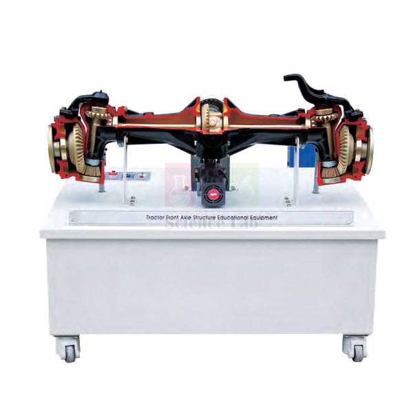
Tractor Differential Gear Model
In the Tractor Differential Gear Model, a single phase 220V, 180W geared motor turns a set of tractor shafts so that trainees can watch the differential, axle and reduction gears drive the wheels. A speed control slows the drive for close study, and parts that stay hidden on a real tractor are opened up and painted in different colours.
Tractor differential model specifications
| Parameter | Detail |
|---|---|
| Drive motor | Single phase 220V, 180W, with mounted reduction gear |
| Composition | Tractor shafts, power switch, power lamp, emergency switch, fuse holder and speed control |
| Systems shown | Differentials, axle, reduction gears and wheel operation |
| Construction | Parts not seen on an actual tractor opened for viewing; each component coloured differently |
| Stand | Steel frame with 5-inch lockable wheels |
| Weight | Approx. 150 kg |
| Size | Approx. 1,500 × 800 × 800 mm |
| Product code | SLE/ATE/27 |
| Minimum order | 10 units |
| Dispatch | Usually within 7 to 10 working days |
| Manufacturer | ScienceLab (Jain Scientific Equipments Pvt Ltd), Ambala, India |
Tractor driveline practicals on the motor-driven model
Pre-start check. Before each session, a trainee locks the wheels of the steel frame, confirms the fuse holder is fitted, turns the speed control fully down and checks that the emergency switch is within reach. Only then is the power switch turned on, with the power lamp confirming the unit is live. The rest of the group stands clear of the gears.
Counting the reduction. With the drive running slowly, chalk a mark on the input shaft and on one wheel. Trainees count input turns for one wheel turn to find the overall reduction, then count again at the shaft between the differential and the reduction gears to see how much each stage contributes.
Where the extra reduction sits. Compare the model with the hand-turned differential gear and the heavy duty vehicles differential gear model. Trainees note that a car-type axle has one reduction at the crown wheel, while tractor and heavy machine axles add a further stage, and they explain why that stage is placed after the differential.
From engine to wheel. Finish by following the drive through the whole tractor: the clutch structure trainer shows how the engine is connected and disconnected, and the large yard tractor engine fault diagnosis system covers the engine side. Trainees then draw the complete power path from the engine to the rear wheels.
Frequently Asked Questions About the Tractor Differential Gear Model
What does the final drive do on a tractor?
The final drive is the last gear reduction between the differential and the rear wheels. It lowers wheel speed and raises torque once more, giving the slow, strong pull needed for ploughing and hauling. Placing it after the differential means the differential and the half shafts carry less torque, so they can be lighter.
Which parts make up a tractor differential, and how does the drive pass through them?
A bevel pinion on the drive shaft turns the crown wheel, which is bolted to the differential case. The case carries small pinions on a cross pin, and these mesh with two side gears splined to the half shafts. The case drives both side gears, and the small pinions let them run at different speeds on turns.
How is the rear axle oil on a tractor checked?
Park the tractor on level ground, let the oil settle and check it at the level plug or dipstick that the operator's manual shows. On many tractors the gearbox and rear axle share one oil. Milky or grey oil means water has got in through condensation or worn seals, so drain it and refill with fresh oil.
How can trainees check a tractor rear axle for worn bearings?
With the axle raised and safely supported, rock the wheel at the top and bottom to feel for play, then turn it slowly and listen for roughness. A growl that rises with travel speed also points to bearing wear. Metal particles on the drain plug confirm that something inside is wearing.
Why run the model at low speed during a lesson?
At low speed trainees can follow each gear by eye, count shaft turns and see the speed fall at every reduction stage. It also gives more time to react. Keep hands, sleeves and pointers away from the open gears, and use the emergency switch at once if anything catches.
Tractor and driveline trainers for a mechanic lab
- Differential Gear
- Heavy Duty Vehicles Differential Gear Model
- Large Yard Tractor Engine Fault Diagnosis System
- Clutch Structure Trainer Mechanical Manual
- Vehicle Transmission 5 Speed Manual Gearbox
To request a quotation, send the product name, code and quantity through our contact page or add the item to your enquiry cart.
Last updated: 14 November 2026