- Physics Lab Equipment
- Chemistry Lab Equipment
- Biology Lab Equipment
- Anatomical Lab Equipment
- Learning
- Educational Lab Equipment
- Magnets
- Agriculture
- Astronomy
- Earth Science
- Geography Lab Equipment
- Safety Lab Coat
- Laboratory
- Meteorological
- Electricity & Magnetism
- Heat
- School Lab Equipment
- Lab Glassware
- Science Lab Equipment
- Tvet Lab Equipment
- Robotics Kits Supplier and Manufacturer for Schools India
- Math Lab Equipment Manufacturers and Exporters in Ambala
- STEM Kits Manufacturers and Supplier India
- Engineering Lab Equipment
- Hospital Lab Equipment
- Water, Sanitation & Hygiene Supplies
- Cold Chain, Solar & Communication Equipment
- Nutrition
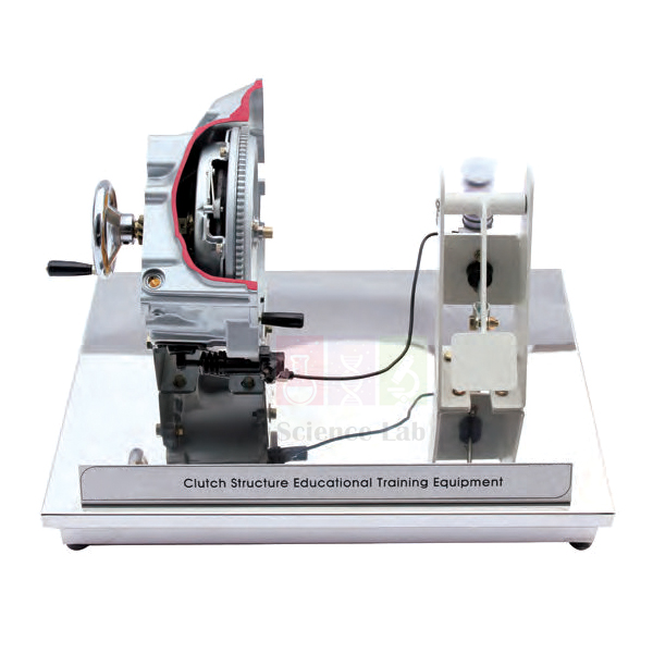
Clutch Structure Trainer Hydraulic Manual
The Clutch Structure Trainer Hydraulic Manual is a hand-operated unit that lays out the hydraulic clutch of a manual-transmission vehicle from pedal to flywheel. It carries the clutch pedal, clutch master cylinder, operating cylinder, clutch pressure board and fly wheel, each cut open and painted in its own colour. Students work the pedal themselves and watch the clutch release in real movement.
Hydraulic manual clutch trainer specifications
| Parameter | Detail |
|---|---|
| Type | Education unit of hydraulic clutch structure in manual transmission |
| Composition | Fly wheel, clutch pressure board, clutch pedal, operating cylinder, clutch master cylinder |
| Operation | Real movement operated directly by hand |
| Sectioning | Each incised section painted in a different colour |
| Weight | Approx. 25 kg |
| Size | Approx. 600 × 400 × 400 mm |
| Product code | SLE/ATE/07 |
| Minimum order | 10 units |
| Dispatch | Usually within 7 to 10 working days |
| Manufacturer | ScienceLab (Jain Scientific Equipments Pvt Ltd), Ambala, India |
Clutch release practicals on the hydraulic manual trainer
Pedal-to-flywheel trace. Press the pedal a little at a time and hold it at each stop. At every stop, students name the part that is moving: master cylinder piston, then the operating cylinder that the fluid pressure reaches, then the release side of the clutch pressure board. Finish by marking where the board lifts away from the fly wheel face.
Pressure transfer first. Open the lesson on a Pascal's principle demonstrator: push its piston and water jets out of every hole in the bulb, showing that pressure in a confined liquid passes equally in all directions. Then return to the trainer and trace the same transfer from the clutch master cylinder, as the input, to the operating cylinder, as the output.
Clutch and brake hydraulics compared. Set the trainer beside a working model of a hydraulic braking system. Both start with a master cylinder at the pedal. Groups note the key difference: in the clutch, springs do the clamping and fluid pressure releases it, while in the brake the fluid pressure does the clamping.
Where the drive goes next. Move on to a five-speed manual gearbox and point out the input shaft that a clutch disc drives on a vehicle. Students then explain why the clutch must be fully released before a gear is selected.
Frequently Asked Questions About the Clutch Structure Trainer Hydraulic Manual
Which part of this trainer is the driving member of the clutch?
The fly wheel. On a vehicle it is bolted to the crankshaft and always turns with the engine. With the pedal up, spring force from the clutch pressure board (pressure plate) clamps the friction disc against the flywheel face, and drive passes to the gearbox.
What moves first when the clutch pedal is pressed?
The piston in the clutch master cylinder. It pushes fluid along the line to the operating cylinder, whose rod works the release side of the clutch pressure board. The board stops clamping, so the flywheel turns without passing drive on. Letting the pedal up reverses the sequence.
What does a spongy pedal mean on a hydraulic clutch?
Usually air in the fluid. Air compresses where fluid does not, so part of the pedal travel is lost squeezing the bubble and the clutch may not release fully. Gears then become hard to select or grind. Bleeding the system removes the air.
Where is a hydraulic clutch bled on a vehicle, and why watch the reservoir?
At the bleed screw on the operating (slave) cylinder, while a helper presses the pedal or a bleeder kit pushes fluid through. Keep the master cylinder reservoir topped up during the job, because a low reservoir draws in fresh air. Close the bleed screw gently, without overtightening.
Why does a slipping clutch give off a burning smell?
The friction lining is rubbing on the flywheel instead of gripping it, so heat builds quickly and the lining glazes or burns. Common causes are a worn lining, weak clamping from the pressure plate, oil on the faces, or a hydraulic fault that holds the clutch partly released.
Clutch, driveline and vehicle hydraulics trainers
- Clutch Structure Trainer Hydraulics
- Clutch Structure Trainer Mechanical Manual
- Vehicle Transmission 5 Speed Manual Gearbox
- Differential Gear
- Working Model Of Hydraulic Braking System
- Automotive Power Train Training Equipment DOHC Gasoline
To request a quotation, send the product name, code and quantity through our contact page or add the item to your enquiry cart.
Last updated: 14 November 2026