- Physics Lab Equipment
- Chemistry Lab Equipment
- Biology Lab Equipment
- Anatomical Lab Equipment
- Learning
- Educational Lab Equipment
- Magnets
- Agriculture
- Astronomy
- Earth Science
- Geography Lab Equipment
- Safety Lab Coat
- Laboratory
- Meteorological
- Electricity & Magnetism
- Heat
- School Lab Equipment
- Lab Glassware
- Science Lab Equipment
- Tvet Lab Equipment
- Robotics Kits Supplier and Manufacturer for Schools India
- Math Lab Equipment Manufacturers and Exporters in Ambala
- STEM Kits Manufacturers and Supplier India
- Engineering Lab Equipment
- Hospital Lab Equipment
- Water, Sanitation & Hygiene Supplies
- Cold Chain, Solar & Communication Equipment
- Nutrition
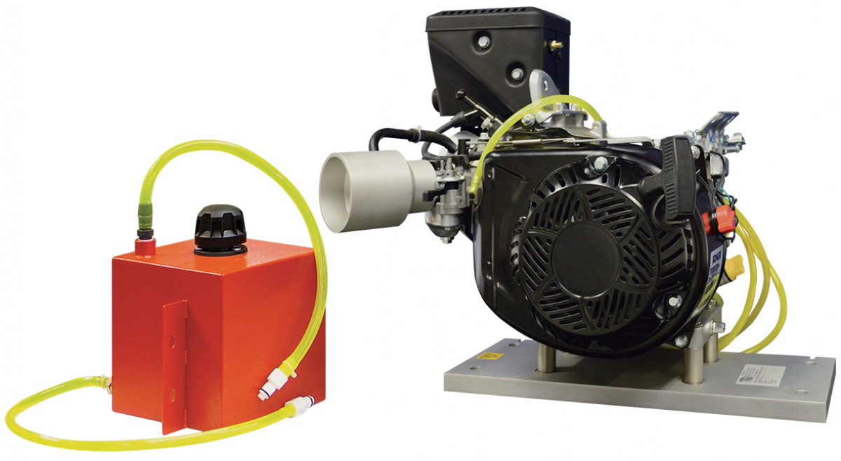
4 Stroke Petrol Engine
Adapted for laboratory testing and demonstrations, this spark-ignition engine runs on a dynamometer test set. It comes with an exhaust thermocouple, a half-coupling for the dynamometer and the essential hoses and fittings, all on a precision bed plate. Quick-release fuel couplings and a removable tank make fuelling and storage between classes simple.
4 stroke petrol test engine details
| Parameter | Detail |
|---|---|
| Engine type | Four-stroke petrol engine adapted for laboratory testing and demonstrations |
| Included fittings | Exhaust thermocouple; half-coupling to the test set dynamometer; essential hoses and fittings |
| Mounting | Precision bed plate with dowels and slots that align and locate it on the dynamometer test set |
| Engine changeover | Bed plate location shortens the time to replace one engine with another |
| Fuel connections | Quick-connect couplings with minimum loss or spillage of fuel |
| Fuel tank | Removable for filling or for storage in a fuel locker; removal also prevents unauthorised use |
| Product code | SLE/EE/02 |
| Minimum order | 10 units |
| Dispatch | Usually within 7 to 10 working days |
| Manufacturer | ScienceLab (Jain Scientific Equipments Pvt Ltd), Ambala, India |
Petrol engine practicals on the dynamometer
Performance curves. Run the engine across a range of speeds and loads, and at each point note torque, speed, fuel flow and the exhaust thermocouple reading. Plot torque and brake power against speed to find where each one peaks, and mark the speed where fuel use per unit of power is least.
Heat balance. Time the fuel flow with the manual volumetric fuel gauge and pass the exhaust through the exhaust gas calorimeter to measure the heat it carries. Set brake power, exhaust heat and cooling loss against the fuel energy and show where the rest went.
Introducing the cycle. Before any engine runs, walk the class through the cut section model of a four stroke petrol engine to show the spark plug, valves and the order of the four strokes. Then point out the same events on the running engine.
End of session routine. Stop the engine, let it cool, part the fuel couplings and lift off the tank for the fuel locker. Students record the shutdown steps in the log so the next batch starts from the same condition.
Frequently Asked Questions About the 4 Stroke Petrol Engine
Why is the fuel tank removable?
Taking the tank off lets it be filled away from the engine and kept in a fuel locker between classes. With the tank removed the engine cannot be started without staff, which stops unsupervised use. Keep the locker closed, labelled and away from heat sources.
How should students handle petrol when fuelling the engine?
Fill the tank with the engine stopped and cool, in a ventilated area with no flames or sparks nearby. Use a small labelled can and pour slowly. The quick couplings limit spillage when lines are joined or parted, but wipe up drips at once and put used rags in a closed bin.
How is a heat balance drawn up from the test readings?
Work out the fuel energy supplied each minute from the fuel rate and its calorific value. Then account for brake power, heat carried off by the exhaust, heat removed by cooling and the unaccounted remainder. Show each share as a percentage of the fuel energy so different loads can be compared.
Why does the heat balance never close exactly?
Some heat leaves by radiation and convection from the hot block and exhaust pipe, and some goes into the oil through friction. Readings taken before temperatures settle add further error. Let the engine run steady at each load before reading, and repeat the fuel timing to reduce scatter.
What does the exhaust thermocouple show as the load changes?
Exhaust temperature climbs as load rises, because more fuel burns each cycle and more heat leaves with the gases. Combined with the exhaust gas flow, the reading gives the exhaust share of the heat balance. Wait for it to settle after each load change before writing it down.
How is the petrol engine joined to the dynamometer?
The engine sits on a precision bed plate whose dowels and slots line it up with the test set. The supplied half-coupling links its output to the dynamometer, and the fuel couplings disconnect quickly, so changing to another engine for the same set takes little time.
Petrol engine test companions
- Manual Volumetric Fuel Gauge
- Exhaust Gas Calori meter
- Exhaust Gas Calorimeter
- 4 Stroke Diesel Engine
- Cut Section Model Of Four Stroke Petrol Engine
- Four Stroke Four Cylinder Petrol Engine Test Bench
To request a quotation, send the product name, code and quantity through our contact page or add the item to your enquiry cart.
Last updated: 20 November 2026