- Physics Lab Equipment
- Chemistry Lab Equipment
- Biology Lab Equipment
- Anatomical Lab Equipment
- Learning
- Educational Lab Equipment
- Magnets
- Agriculture
- Astronomy
- Earth Science
- Geography Lab Equipment
- Safety Lab Coat
- Laboratory
- Meteorological
- Electricity & Magnetism
- Heat
- School Lab Equipment
- Lab Glassware
- Science Lab Equipment
- Tvet Lab Equipment
- Robotics Kits Supplier and Manufacturer for Schools India
- Math Lab Equipment Manufacturers and Exporters in Ambala
- STEM Kits Manufacturers and Supplier India
- Engineering Lab Equipment
- Hospital Lab Equipment
- Water, Sanitation & Hygiene Supplies
- Cold Chain, Solar & Communication Equipment
- Nutrition
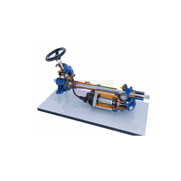
Cut Model Of Rack And Pinion Steering
The Cut Model Of Rack And Pinion Steering is a sectioned model: turn its crank handle and the pinion drives the rack sideways, just as it does when a driver turns the steering wheel. Beside the rack type steering box, the tubular frame carries a hydraulic pump, an oil tank with its filter and the connecting pipes, so students can trace the power-assist circuit as well as the gears.
Rack and pinion steering model specifications
| Parameter | Detail |
|---|---|
| Steering type | Rack and pinion, rack type steering box |
| Hydraulic components | Hydraulic pump; oil tank with filter; connecting pipes |
| Operation | Manual, by crank handle |
| Mounting | Tubular frame on a base |
| Finish | Imported colour paint with gloss coating; hardware and gears electroplated |
| Dimensions | 1000 × 600 × 550 mm |
| Weight | Approx. 25 kg |
| Product code | SLE/MCE/64 |
| Minimum order | 10 units |
| Dispatch | Usually within 7 to 10 working days |
| Manufacturer | ScienceLab (Jain Scientific Equipments Pvt Ltd), Ambala, India |
Steering exercises with the rack and pinion model
Rack travel per pinion turn. Mark the crank handle and the rack, turn the handle through one full turn and measure how far the rack moves with a vernier caliper or steel rule. Then count the turns from one end of travel to the other and work out the total rack stroke.
Tracing the power-assist circuit. Follow the pipes from the oil tank and filter to the hydraulic pump, on to the steering box and back again. Students label the pressure and return lines and say where a leak or trapped air would make the steering heavy. The power steering gear trainer gives a second design to compare.
Fluid pressure in chassis systems. Set the model next to the working model of hydraulic braking system and compare how each system uses fluid under pressure. Power steering oil helps the driver push the rack, while brake fluid applies the brakes at the wheels.
Wheels on a bend. Sketch the tie rods and steering arms that the rack would push, mark the turning centre and show why the inner wheel must turn more sharply. The differential gear then explains how the driven wheels cope with the different path lengths.
Frequently Asked Questions About the Cut Model Of Rack And Pinion Steering
How does a rack and pinion turn the front wheels?
The pinion sits on the end of the steering shaft and meshes with teeth cut along the rack. Turning the pinion slides the rack to one side, and tie rods at each end push the steering arms on the wheel hubs. On the model, the crank handle takes the place of the steering wheel.
What is the difference between hydraulic and electric power steering?
Hydraulic assist uses a pump to send oil from a reservoir to a control valve at the pinion, which directs pressure to one side of a piston on the rack. Electric power steering uses a motor on the column or rack and needs no oil. This model shows the hydraulic type, with pump, oil tank, filter and pipes.
Why does power steering suddenly become heavy?
Check the simple causes first: low oil in the tank, a slipping or broken pump belt, or low tyre pressure. If those are fine, suspect a weak pump, air in the system or worn seals inside the rack. On the model, students can point to where each fault would occur.
Where do power steering leaks usually appear?
Look at the pipe unions, the pump shaft seal, the reservoir and the rubber boots at each end of the rack, where worn inner seals let oil collect. Tracing the pipe route on the model from oil tank to pump to steering box shows every joint that needs checking.
What is Ackermann steering geometry for?
On a bend, the inner front wheel follows a tighter circle than the outer one, so it must turn through a larger angle. Angled steering arms joined to the rack by tie rods give this difference, letting both wheels roll around a common centre without scrubbing the tyres.
What does steering ratio mean on a rack and pinion system?
It compares how far the steering wheel turns with how far the road wheels turn. A smaller pinion, or a pinion with fewer teeth, moves the rack less per turn and gives a slower, lighter ratio. Students can find the rack travel per turn on the model and relate it to wheel angle.
Steering, braking and driveline trainers
- Power Steering Gear
- Working Model Of Hydraulic Braking System
- ABS Braking System Training Board Simulator
- Differential Gear
- Vehicle Transmission 5 Speed Manual Gearbox
To request a quotation, send the product name, code and quantity through our contact page or add the item to your enquiry cart.
Last updated: 14 November 2026