- Physics Lab Equipment
- Chemistry Lab Equipment
- Biology Lab Equipment
- Anatomical Lab Equipment
- Learning
- Educational Lab Equipment
- Magnets
- Agriculture
- Astronomy
- Earth Science
- Geography Lab Equipment
- Safety Lab Coat
- Laboratory
- Meteorological
- Electricity & Magnetism
- Heat
- School Lab Equipment
- Lab Glassware
- Science Lab Equipment
- Tvet Lab Equipment
- Robotics Kits Supplier and Manufacturer for Schools India
- Math Lab Equipment Manufacturers and Exporters in Ambala
- STEM Kits Manufacturers and Supplier India
- Engineering Lab Equipment
- Hospital Lab Equipment
- Water, Sanitation & Hygiene Supplies
- Cold Chain, Solar & Communication Equipment
- Nutrition
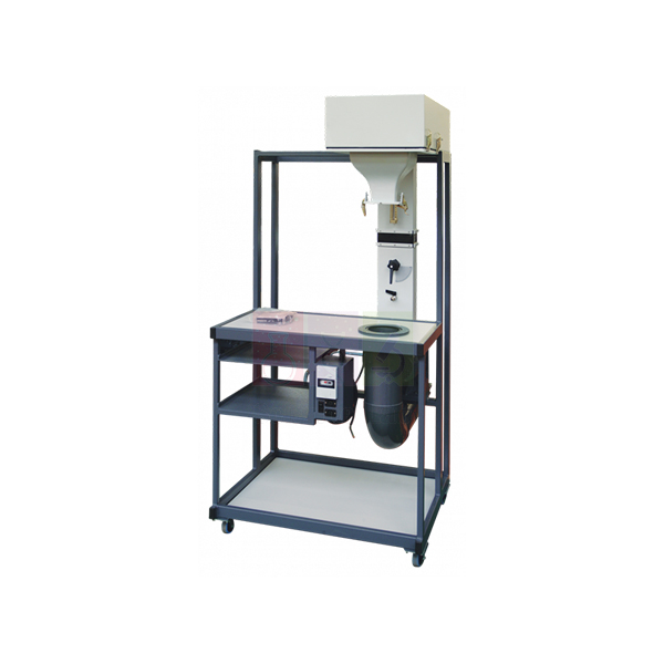
Modular Air Flow Bench
Modular Air Flow Bench is a small-scale wind tunnel base unit that supplies controlled air to interchangeable experiment modules. An electric fan on a steel frame feeds air through a flow-control valve into a plenum chamber and a shaped contraction, where each module fits. One bench serves eight different modules, and quick-release pressure couplings make changeovers fast.
Modular Air Flow Bench design
| Parameter | Detail |
|---|---|
| Type | Small-scale wind tunnel with electric fan and adjustable air flow control |
| Experiment modules served | Base unit for eight different air-flow modules |
| Frame | Steel framework carrying the fan |
| Air path | Fan, flow-control valve, plenum chamber and aerodynamically shaped contraction |
| Module mounting | Each module fits either the plenum chamber or the contraction |
| Exhaust | Air leaves the module through the bench top to an exhaust at the rear |
| Pressure connections | Quick-release couplings |
| Smoke experiments | Flexible ducting can be fitted to the exhaust to lead waste smoke away |
| Storage | Shelves for modules not in use; compact bench, easy to move and store |
| Product code | SLE/EA/01 |
| Minimum order | 10 units |
| Dispatch | Usually within 7 to 10 working days |
| Manufacturer | ScienceLab (Jain Scientific Equipments Pvt Ltd), Ambala, India |
Running air-flow practicals on the bench
Jet studies. Fit a jet experiment such as the Effect And Jet Flow module, once its fit with the bench has been confirmed. Open the flow-control valve gradually and record how the jet behaves at each setting. Air is invisible, so add smoke when the class needs to see the jet.
Pressure readings. Connect the module's tappings through the quick-release couplings to a U tube manometer. After each valve change, wait until the liquid levels stop moving before you read. Record the valve setting with every set of readings so runs can be compared.
Smoke runs. Fit flexible ducting to the rear exhaust and lead it to a window or extraction point. Smoke from the Flow Visualisation smoke set then shows the flow pattern while the spent smoke leaves the room.
Changing over. Release the couplings, lift off the module and fit the next one to the plenum or the contraction. Store unused modules on the bench shelves so their fittings stay clean.
Frequently Asked Questions About the Modular Air Flow Bench
What does the plenum chamber do?
Air from the fan and valve enters a large chamber where it slows and its pressure evens out. The module therefore receives a steady, uniform supply instead of a jet straight from the fan. The shaped contraction then speeds the air up smoothly for modules that need a faster stream.
Why wait before taking readings after changing the valve?
The plenum pressure and the flow through the module take a little time to settle after each change. Readings taken too early drift as the system steadies. Wait until the manometer levels stop moving, then read, and repeat the reading once to confirm it.
Does it matter where the manometer tubes are connected?
Yes. Each tapping gives the pressure at its own point, so a tube on the wrong tapping gives a wrong result. Label the tubes, follow the module instructions, keep the tubes free of kinks and level the manometer before reading at eye level.
How is air speed worked out from manometer readings?
Measure the difference between total and static pressure, which is the dynamic pressure. Convert the manometer height to pressure using the manometer liquid density and gravity. The air speed is then the square root of twice the dynamic pressure divided by the air density.
Why repeat a module test at several flow settings?
Changing the valve setting changes the air speed and so the Reynolds number of the flow. Separation, transition to turbulence and jet behaviour all depend on it. Results at several settings show the trend rather than a single point.
Modules and units for air-flow teaching
- Effect And Jet Flow
- Flow Visualisation
- Flow Visualisation Wind Tunnel
- Subsonic Wind Tunnel
- Schlieren Apparatus
To request a quotation, send the product name, code and quantity through our contact page or add the item to your enquiry cart.
Last updated: 14 November 2026