- Physics Lab Equipment
- Chemistry Lab Equipment
- Biology Lab Equipment
- Anatomical Lab Equipment
- Learning
- Educational Lab Equipment
- Magnets
- Agriculture
- Astronomy
- Earth Science
- Geography Lab Equipment
- Safety Lab Coat
- Laboratory
- Meteorological
- Electricity & Magnetism
- Heat
- School Lab Equipment
- Lab Glassware
- Science Lab Equipment
- Tvet Lab Equipment
- Robotics Kits Supplier and Manufacturer for Schools India
- Math Lab Equipment Manufacturers and Exporters in Ambala
- STEM Kits Manufacturers and Supplier India
- Engineering Lab Equipment
- Hospital Lab Equipment
- Water, Sanitation & Hygiene Supplies
- Cold Chain, Solar & Communication Equipment
- Nutrition
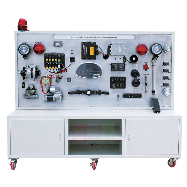
Wheel Loaders Electric Circuit Training Simulator
The Wheel Loaders Electric Circuit Training Simulator opens out the electric circuit of a heavy machinery wheel loader on one frame, so trainees can see each part and how it behaves. It runs on a DC 24 V battery and carries an ECU, relays, a starter motor, levers and digital meters for measuring the input and output of every component.
Wheel loader circuit simulator specifications
| Parameter | Detail |
|---|---|
| Basis | Electric circuit equipment using a heavy machinery wheel loader |
| Power | DC 24 V battery |
| Composition | ECU, battery, operating lever, light system, horn, hydraulic lever, starter motor, battery connector, relay, digital meters |
| Meters | Two ammeters and two voltmeters, plus digital meters |
| Layout | Parts not visible on an actual machine are opened out to show their operating state and location |
| Training content | Measuring the input and output data in each component |
| Weight | Approx. 350 kg |
| Size | Approx. 2,000 × 600 × 1,700 mm |
| Product code | SLE/ATE/22 |
| Minimum order | 10 units |
| Dispatch | Usually within 7 to 10 working days |
| Manufacturer | ScienceLab (Jain Scientific Equipments Pvt Ltd), Ambala, India |
Circuit exercises on the wheel loader simulator
Battery and connector baseline. With every switch off, trainees read the 24 V battery on a standard digital multimeter. They read it again with the light system on and once more while the starter motor turns. A large drop measured across the battery connector itself points to a poor contact rather than a weak battery.
Lever inputs and ECU outputs. One trainee moves the operating lever and the hydraulic lever through each position while a partner logs the signal reaching the ECU and the output it sends on. The finished table of input and output values becomes the reference sheet for later fault tracing.
Relay checks. Find the relay in the circuit and follow the wires from it to the loads it feeds. Compare the voltage at the relay input with the voltage at its output, and explain where the current would stop if the relay failed to close. Isolate the battery connector before any wire is moved.
Two earth-moving machines. Repeat the input and output tests on the excavator electric circuit training simulator and mark on a shared sheet the parts that differ between the two machines. Groups moving on to drivelines can continue with the heavy duty vehicles differential gear model.
Frequently Asked Questions About the Wheel Loaders Electric Circuit Training Simulator
Why does a wheel loader use a 24 V system?
Doubling the voltage halves the current needed for the same power. Cables can then be thinner, and the starter motor of a large diesel engine gets more cranking power. Many machines build the 24 V supply from two batteries connected in series.
Why learn to read the wiring diagram before tracing a fault?
The diagram shows where each wire runs, which relay feeds which load and where the circuit is earthed. Trainees who know its symbols test points in a logical order instead of guessing, and can compare every meter reading with what the diagram says should be there.
Can a 24 V battery circuit hurt someone?
The shock from 24 V is usually slight, but the battery can push a very large current through a short circuit. A spanner or ring across the terminals can heat up, burn skin and throw sparks. Remove rings and watches, and disconnect the battery connector before changing any wiring.
What should be checked first when a loader keeps needing a jump start?
Start with the battery itself: clean terminals, a tight connector and a resting voltage close to its rating. A load test then shows whether it holds voltage under demand. Only when the battery passes is the charging output measured with a multimeter while the engine runs.
What does the ECU do in the loader circuit?
On a machine, the ECU reads signals from the levers and switches and controls outputs such as relays in response. On the simulator, measuring at its input and at its output shows whether a fault lies before the ECU, inside it or in the wiring after it.
Heavy machinery trainers and test meters
- Excavator Electric Circuit Training Simulator
- Electric Forklift Electric Circuit Training Simulator
- Standard Digital Multimeter
- Heavy Duty Vehicles Differential Gear Model
- Digital Multimeter
To request a quotation, send the product name, code and quantity through our contact page or add the item to your enquiry cart.
Last updated: 15 November 2026