- Physics Lab Equipment
- Chemistry Lab Equipment
- Biology Lab Equipment
- Anatomical Lab Equipment
- Learning
- Educational Lab Equipment
- Magnets
- Agriculture
- Astronomy
- Earth Science
- Geography Lab Equipment
- Safety Lab Coat
- Laboratory
- Meteorological
- Electricity & Magnetism
- Heat
- School Lab Equipment
- Lab Glassware
- Science Lab Equipment
- Tvet Lab Equipment
- Robotics Kits Supplier and Manufacturer for Schools India
- Math Lab Equipment Manufacturers and Exporters in Ambala
- STEM Kits Manufacturers and Supplier India
- Engineering Lab Equipment
- Hospital Lab Equipment
- Water, Sanitation & Hygiene Supplies
- Cold Chain, Solar & Communication Equipment
- Nutrition
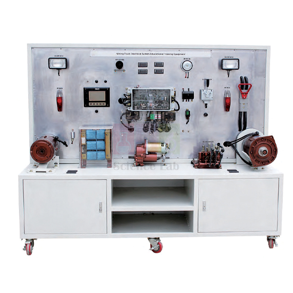
Electric Forklift Electric Circuit Training Simulator
The Electric Forklift Electric Circuit Training Simulator is a training panel built from the electrical circuit device of a left-seat type electric forklift. It opens out the battery, levers, relays, instrument panel and motors that stay hidden on a working truck. Trainees measure the voltage and current of the driven rotor and the hydraulic rotor while the circuit operates, and record the input and output data at each component.
Electric forklift circuit simulator specifications
| Parameter | Detail |
|---|---|
| Basis | Electrical circuit device of a left-seat type electric forklift |
| Composition | Battery, operating lever, light system, horn, hydraulic lever, instrument panel, starter motor, battery connector, relay, digital meters and other parts |
| Live measurements | Voltage and current of the driven rotor and the hydraulic rotor during operation |
| Layout | Parts hidden on an actual forklift opened out to show their operating state and location |
| Training content | Measuring the input/output data in each component |
| Weight | Approx. 350 kg |
| Size | Approx. 2,000 × 600 × 1,700 mm |
| Product code | SLE/ATE/23 |
| Minimum order | 10 units |
| Dispatch | Usually within 7 to 10 working days |
| Manufacturer | ScienceLab (Jain Scientific Equipments Pvt Ltd), Ambala, India |
Circuit practicals on the forklift simulator
Reference readings. With the circuit working normally, students operate each function in turn and log the voltage and current shown on the digital meters, then check the input and output values at every component with an advanced digital multimeter. The completed sheet becomes the reference for later fault tracing.
Travel against lift. Compare the current taken by the driven rotor as the operating lever is moved with the current taken by the hydraulic rotor when the hydraulic lever is used. Watch the battery voltage at the same time and discuss how each load drains the battery, a topic that continues on the electric vehicle energy management training equipment.
Relays and simple circuits. Start with the light system and horn, the easiest circuits to follow. Then measure the relay coil voltage when it is switched and the voltage drop across its contacts under load. Take live readings with the meter probes only, and isolate the battery connector before touching, disconnecting or refitting any terminal or wire.
Battery-electric against engine-driven machines. Finish by setting the forklift circuit beside the wheel loaders electric circuit training simulator and listing which parts each machine needs to start, drive and work its hydraulics.
Frequently Asked Questions About the Electric Forklift Electric Circuit Training Simulator
Why might an electric forklift not travel forward or in reverse?
Work along the circuit in order. Check the battery connector and battery voltage, the key and direction selection, then whether the main contactor closes and passes full voltage. Next check the direction contactors and the drive signal. On the simulator, measuring the input and output at each component builds the same habit.
What does a contactor or relay do, and how is it tested?
It is a switch worked by a coil: a small control current closes contacts that carry a much larger current. First check that the coil receives its voltage when switched. Then measure the voltage drop across the closed contacts under load, because burnt contacts show a high drop even when the coil works.
How is the speed of an electric forklift drive motor controlled?
Older trucks switched resistors in and out of the motor circuit in steps. Modern trucks use a solid-state controller that varies the average voltage or frequency supplied to the motor. On the simulator, students watch the driven rotor voltage and current change as the operating lever is moved.
Is a digital multimeter enough for forklift circuit tests?
For battery voltage, voltage drops, coil checks, continuity and resistance, yes. Motor current is far higher than a multimeter's own current range, so never connect the meter in series with a motor. Read current on the simulator's digital meters, across a shunt, or with a clamp meter.
Why did older resistor-controlled forklifts run hot and lurch?
The resistors lowered motor voltage by turning the extra energy into heat, so the controller grew hot, especially at low speed. Each contactor step changed the motor voltage suddenly, which made the truck jerk as it gathered speed. Solid-state controllers replaced this with smooth, more efficient control.
What does a current shunt or sensor in a forklift motor circuit do?
It tells the controller how much current the motor is drawing. A shunt is a low-resistance strip whose voltage drop rises in step with current. If the shunt or sensor fails, the controller may cut power or refuse to drive, so check its signal before replacing larger parts.
Electrical vehicle trainers and test meters
- Electric Vehicle Energy Management Training Equipment
- Excavator Electric Circuit Training Simulator
- Wheel Loaders Electric Circuit Training Simulator
- Advanced Digital Multimeter
- Digital Multimeter
To request a quotation, send the product name, code and quantity through our contact page or add the item to your enquiry cart.
Last updated: 14 November 2026