- Physics Lab Equipment
- Chemistry Lab Equipment
- Biology Lab Equipment
- Anatomical Lab Equipment
- Learning
- Educational Lab Equipment
- Magnets
- Agriculture
- Astronomy
- Earth Science
- Geography Lab Equipment
- Safety Lab Coat
- Laboratory
- Meteorological
- Electricity & Magnetism
- Heat
- School Lab Equipment
- Lab Glassware
- Science Lab Equipment
- Tvet Lab Equipment
- Robotics Kits Supplier and Manufacturer for Schools India
- Math Lab Equipment Manufacturers and Exporters in Ambala
- STEM Kits Manufacturers and Supplier India
- Engineering Lab Equipment
- Hospital Lab Equipment
- Water, Sanitation & Hygiene Supplies
- Cold Chain, Solar & Communication Equipment
- Nutrition
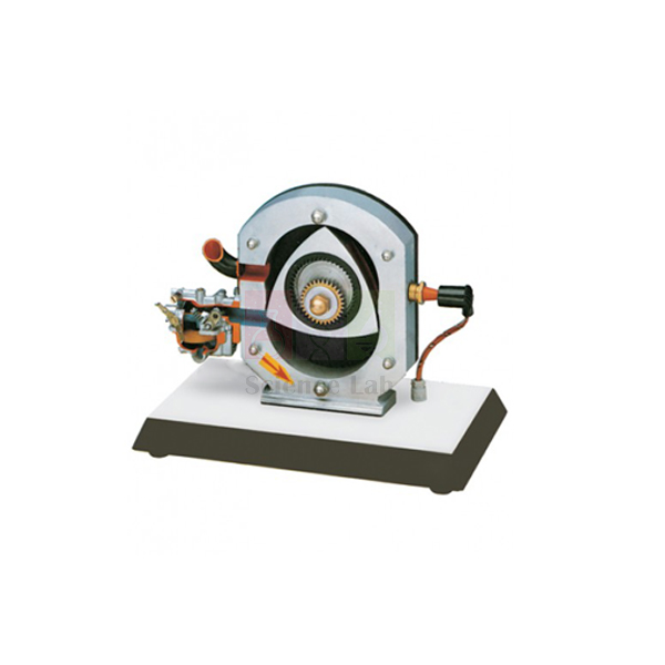
Wankel Engine Model
The Wankel Engine Model shows how a triangular rotor, turned by the driving shaft inside a sectioned stator, produces every working phase of a rotary engine. It is worked by a crank handle and built of light metal, with its parts, cross sections and fuel system painted in different colours. A small bulb lights at the compression phase to simulate ignition.
Wankel engine model specifications
| Parameter | Detail |
|---|---|
| Engine type | Wankel (rotary) engine, cut-away for training |
| Rotor | Triangular piston operated by the driving shaft, rotating inside the stator and showing the different phases |
| Ignition simulation | Small bulb lights up at the compression phase |
| Construction | Light metal; various parts cross-sectioned to show internal operation |
| Colour coding | Parts, cross sections and fuel system painted in different colours |
| Operation | Manual, by crank handle |
| Mounting | On a base with wheel |
| Dimensions | 350 × 400 × 300 mm |
| Weight | Approx. 7 kg |
| Product code | SLE/MCE/66 |
| Minimum order | 10 units |
| Dispatch | Usually within 7 to 10 working days |
| Manufacturer | ScienceLab (Jain Scientific Equipments Pvt Ltd), Ambala, India |
Rotary engine lessons with the sectioned model
Following one rotor face. Fix a small paper tag to one face of the rotor and turn the crank handle slowly. Students record the order in which that face passes intake, compression, the bulb flash, power and exhaust. They also count crank turns for one full turn of the rotor and compare the count with the textbook relationship.
Three chambers at once. Stop the crank at any point and ask each student to name the phase taking place in each of the three chambers around the rotor. Repeat at the moment the bulb lights, so the class links the smallest chamber volume with the point of ignition.
Rotary against reciprocating. Set the model beside the four stroke petrol engine cut section and list the parts that must move to complete one cycle in each engine. Students compare valves, camshaft, piston and connecting rod with the rotor and shaft, then discuss why the rotary engine is compact but harder to seal.
Heat engines in sequence. The steam engine model and the hand-powered engine models round off a lesson on how heat engines developed, from the steam piston to the internal combustion rotor.
Frequently Asked Questions About the Wankel Engine Model
How can one rotor carry out intake, compression, power and exhaust at the same time?
The rotor has three faces, and each face forms its own chamber with the housing. As the rotor turns, every chamber passes the intake port, the compression zone, the ignition point and the exhaust port in turn. At any moment the three chambers are therefore in different phases of the same cycle.
What shapes are the rotor and the housing?
The rotor is a curved triangle, close in form to a Reuleaux triangle. The housing, or stator, is an epitrochoid, a rounded shape pinched in at the middle like a broad figure of eight. Its curve lets all three rotor tips stay close to the wall throughout each turn.
How does the rotor turn the output shaft?
The rotor rides on an eccentric lobe of the shaft, and internal gearing keeps it in step as it orbits. The shaft turns three times for each turn of the rotor. Each face fires once per rotor turn, so a single rotor gives one power impulse for every turn of the shaft.
Why are Wankel engines hard to seal?
The seals at the three rotor tips slide along the housing at high speed and pass through hot and cold zones of the stator. They have no thick oil film to ride on, unlike piston rings. As they wear, gas leaks from one chamber to the next and compression falls.
Why do rotary engines use more fuel and oil than piston engines?
The combustion chamber is long, thin and moving, so the flame struggles to reach the trailing part before the exhaust opens, and some fuel leaves unburned. Oil is also fed deliberately into the chambers to lubricate the tip seals, and it burns along with the fuel.
What does the bulb on the Wankel Engine Model show?
It lights at the compression phase, at the point where a spark would fire the mixture in a running engine. Watching the rotor position each time the bulb lights helps students see that ignition comes when the chamber is close to its smallest volume.
Engine models for an engine theory class
- Steam Engine Model
- Cut Section Model Of Four Stroke Petrol Engine
- Section Model Of Four-Stroke Diesel Engine
- Hand-Powered Engine Models
- Stirling Engine
To request a quotation, send the product name, code and quantity through our contact page or add the item to your enquiry cart.
Last updated: 14 November 2026