- Physics Lab Equipment
- Chemistry Lab Equipment
- Biology Lab Equipment
- Anatomical Lab Equipment
- Learning
- Educational Lab Equipment
- Magnets
- Agriculture
- Astronomy
- Earth Science
- Geography Lab Equipment
- Safety Lab Coat
- Laboratory
- Meteorological
- Electricity & Magnetism
- Heat
- School Lab Equipment
- Lab Glassware
- Science Lab Equipment
- Tvet Lab Equipment
- Robotics Kits Supplier and Manufacturer for Schools India
- Math Lab Equipment Manufacturers and Exporters in Ambala
- STEM Kits Manufacturers and Supplier India
- Engineering Lab Equipment
- Hospital Lab Equipment
- Water, Sanitation & Hygiene Supplies
- Cold Chain, Solar & Communication Equipment
- Nutrition
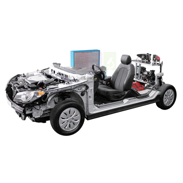
LPI Engine Fault Diagnosis Training Equipment Auto Fault
The LPI Engine Fault Diagnosis Training Equipment Auto Fault combines a 1,600cc LPI engine, a hybrid motor and an automatic transmission on one stand for hybrid fault diagnosis. A hybrid control unit links the ECU, TCM, BMS ECU, MCU and LDC over CAN, and trainees work at a front panel with a display, an education check terminal and toggle switches.
LPI hybrid fault trainer specifications
| Parameter | Detail |
|---|---|
| Powertrain | 1,600cc LPI engine (I4 1.6, 1,591cc), hybrid motor and automatic transmission |
| Control network | HCU (hybrid control unit) connected to ECU, TCM, BMS ECU, MCU and LDC by CAN communication |
| Sensors attached | Slant angle sensor, brake boost pressure sensor |
| Hybrid functions shown | Hybrid engine start; power support at idle or slow movement; driving force support when accelerating; energy recovery (battery charge) when decelerating, with brake switch |
| Front control panel | Display panel, ECU circuit, education check terminal, toggle switches; the panel displays engine start and engine status |
| Diagnosis | With diagnosis equipment: sensor check, short circuit, failure diagnosis and output power |
| Weight and size | Approx. 1,300 kg; approx. 4,600 × 1,800 × 1,500 mm |
| Engine, motor and transmission | Sourced production units; the training stand and front control panel are made by ScienceLab in Ambala |
| Optional items | Laptop, 4-channel oscilloscope and 61 cm (24 inch) LED monitor |
| Product code | SLE/ATE/20 |
| Minimum order | 10 units |
| Dispatch | Usually within 7 to 10 working days |
| Manufacturer | ScienceLab (Jain Scientific Equipments Pvt Ltd), Ambala, India |
Hybrid diagnosis exercises on the LPI trainer
Mode by mode. The instructor runs the trainer through hybrid start, power support at idle, driving force support on acceleration and energy recovery on deceleration with the brake switch. Students note on the display panel when the engine starts and how its status changes, and say which unit on the network commands each step.
Network fault tracing. With diagnosis equipment connected, students read the stored codes from each control unit on the CAN network. They then check supply, ground and network wiring at the education check terminal with an advanced digital multimeter. With the optional 4-channel oscilloscope, they view the network signal to tell a wiring fault from a failed unit.
Sensor and output checks. Trainees test the slant angle sensor and the brake boost pressure sensor, look for short circuits and confirm output power with the diagnosis equipment. Before touching the hybrid motor or battery wiring, isolate the high-voltage system as the supplied operating instructions describe and wear insulating gloves.
A course pathway. Engine control basics come first on the engine management system (MPI) trainer, and this unit then adds the hybrid layer. The electric vehicle energy management training equipment continues the study of battery energy flow in a fully electric drive.
Frequently Asked Questions About the LPI Engine Fault Diagnosis Training Equipment Auto Fault
What does the LDC do on this hybrid powertrain?
The LDC is the low-voltage DC-DC converter. It steps the high voltage of the hybrid battery down to the low-voltage system that runs the lamps, control units and accessories, doing the job an alternator does on a conventional car. If it fails, the low-voltage battery slowly runs down even though the hybrid battery is charged.
How can a fault in one control unit show up as a code in another?
Each unit on the CAN network expects regular messages from the others. When one unit loses power, ground or its network connection, the other units store lost-communication codes, often called U-codes. Trainees check the supply and ground of the silent unit first, then the CAN wiring and connectors, before blaming the unit itself.
How is a network fault told apart from a hybrid battery fault?
A network fault usually sets lost-communication codes in several control units at once. A hybrid battery fault is reported by the BMS ECU itself, while the other units on the CAN network keep talking normally. Reading the codes from every unit, not just one, shows which kind of fault is present.
Which hybrid operating modes does the trainer show?
The listed modes are hybrid engine start, power support at idle or slow movement, driving force support when accelerating, and energy recovery when decelerating, when the motor works as a generator and recharges the battery. On a vehicle, the HCU chooses the mode from driver demand and battery charge. The display panel shows engine start and engine status.
How is energy recovery shared with the friction brakes?
When the brake switch signals braking, the motor control unit lets the motor work as a generator, which slows the vehicle and charges the battery. The friction brakes supply whatever braking the motor cannot, such as at very low speed or in a hard stop. Trainees link this to the energy recovery mode shown on the trainer.
What is LPI, and how does it differ from an LPG mixer system?
LPI injects LPG as a liquid. A pump in the tank keeps the gas liquid under pressure, and injectors spray it into each intake port, much like petrol injection. An older mixer system turns the LPG into vapour and draws it into the intake air, which gives poorer cold starts and less precise fuel metering.
Hybrid and engine control trainers and test instruments
- Electric Vehicle Energy Management Training Equipment
- Engine management system (MPI)
- Automotive Engine Fault Diagnosis Simulator Auto Fault
- Diesel Engine Fault Diagnosis Training Equipment Auto Fault
- Advanced Digital Multimeter
- Oscilloscope Dual Trace
To request a quotation, send the product name, code and quantity through our contact page or add the item to your enquiry cart.
Last updated: 14 November 2026