- Physics Lab Equipment
- Chemistry Lab Equipment
- Biology Lab Equipment
- Anatomical Lab Equipment
- Learning
- Educational Lab Equipment
- Magnets
- Agriculture
- Astronomy
- Earth Science
- Geography Lab Equipment
- Safety Lab Coat
- Laboratory
- Meteorological
- Electricity & Magnetism
- Heat
- School Lab Equipment
- Lab Glassware
- Science Lab Equipment
- Tvet Lab Equipment
- Robotics Kits Supplier and Manufacturer for Schools India
- Math Lab Equipment Manufacturers and Exporters in Ambala
- STEM Kits Manufacturers and Supplier India
- Engineering Lab Equipment
- Hospital Lab Equipment
- Water, Sanitation & Hygiene Supplies
- Cold Chain, Solar & Communication Equipment
- Nutrition
Power & Energy Systems Trainers are the protection-relay, distribution, transformer, converter and load-bank apparatus, together with solar thermal collectors and photovoltaic cells, that electrical engineering and energy courses use to show how power is generated, protected, distributed and consumed. Jain Scientific Equipments Pvt Ltd (ScienceLab), Ambala is the OEM that manufactures the power-system, distribution, transformer, converter, load-bank and solar trainers in this range at its own licensed factory in Ambala, and it supplies the protection relays and the stroboscope, for engineering colleges, polytechnics and ITIs.
What Does the Power & Energy Systems Trainers Range Include?
| Topic | What it covers | Example products |
|---|---|---|
| Protection relays | Overcurrent, earth-fault, differential and distance protection | Overcurrent And Earth Fault Relay, Differential Protection Relay, Distance Protection Relay, Directional/Non-Directional Overcurrent Relay |
| Power systems and distribution | Generation, network simulation, distribution and switching | Modular Power System, Power System Simulator Generator, Distribution Trainer, Circuit Breaker Trainer |
| Transformers and power electronics | Three-phase transformer work and rectifier or converter circuits | Three-phase Mobile Transformer, Thyristor and Diode Converters |
| Load banks | Resistive, inductive and power-factor loading of circuits | Portable Resistive Load Bank, Portable Inductive Load Bank, Power Factor Load Bank |
| Solar thermal and photovoltaic | Collector studies and solar-cell experiments | Focusing Solar Energy Collector, Flat Plate Solar Thermal Energy Collector, Photovoltaic Cells |
| Measurement | Observing rotating or vibrating parts | Stroboscope |
Featured Power & Energy Systems Trainers
| Product | Product Code | Typical Use |
|---|---|---|
| Overcurrent And Earth Fault Relay | SLE/EPS/01 | Studying relay operation under overcurrent and earth faults |
| Distance Protection Relay | SLE/EPS/12 | Teaching distance protection of transmission lines |
| Distribution Trainer | SLE/EPS/02 | Demonstrating how a power distribution network works |
| Power System Simulator Generator | SLE/EPS/04 | Generator-side experiments within a power-system lab |
| Three-phase Mobile Transformer | SLE/EPS/05 | Three-phase transformer connections and tests |
| Thyristor and Diode Converters | SLE/EPS/07 | Rectifier and converter circuits in power electronics |
| Power Factor Load Bank | SLE/EPS/11 | Loading circuits at different power factors |
| Flat Plate Solar Thermal Energy Collector | SLE/ESA/06 | Solar water-heating and collector performance studies |
OEM Manufacturing & Supply
ScienceLab (Jain Scientific Equipments Private Limited) is the OEM for the modular power system, generator simulator, distribution and circuit-breaker trainers, three-phase transformer, converters, load banks, solar collectors and photovoltaic cells in this range, and manufactures them at its own licensed factory at 449, HSIIDC Industrial Area, Saha, Ambala, Haryana. The four protection relays and the stroboscope are supplied rather than made in-house. Electrical departments, polytechnics, ITIs, dealers, tender buyers and importers in India and international markets receive factory-direct supply, and every quotation is issued by the manufacturer itself. The parent company is registered as an MSME with manufacturing as its major activity (Udyam UDYAM-HR-01-0003714) and carries Legal Entity Identifier 3358004HRD1JIVXKYX49 for international buyers.
Related Ranges
- Engineering Lab Equipment – the parent hub for every engineering sub-range.
- Renewable Energy Kits Manufacturer and Supplier Ambala – school-level renewable-energy kits, simpler than the engineering trainers here.
- Solar Energy Kits supplier and Exporter Ambala – classroom solar kits for science lessons rather than engineering labs.
- Electricity & Magnetism – foundation electrical apparatus taught before power-system trainers.
- Thermodynamics & Heat Transfer Lab Equipment – heat-exchanger and heat-transfer rigs that pair with the solar thermal collectors.
Frequently Asked Questions
What do the Power & Energy Systems Trainers include?
Power & Energy Systems Trainers include overcurrent, earth-fault, differential and distance protection relays, a modular power system, generator simulator, distribution and circuit-breaker trainers, a three-phase transformer, thyristor and diode converters, load banks, solar collectors, photovoltaic cells and a stroboscope.
Which courses use power and energy systems trainers?
Power and energy systems trainers are used in electrical engineering labs for power systems, switchgear and protection, power electronics and renewable energy at engineering colleges, polytechnics and ITIs, where students work hands-on with relays, loads and converters.
Who manufactures ScienceLab power and energy systems trainers?
Jain Scientific Equipments Private Limited, trading as ScienceLab, manufactures most power and energy systems trainers in this range, including the power-system, distribution, transformer, converter, load-bank and solar apparatus, at its licensed factory at 449, HSIIDC Industrial Area, Saha, Ambala. The protection relays and the stroboscope are supplied.
How do these trainers differ from school solar and renewable energy kits?
These power and energy systems trainers are engineering-lab apparatus such as protection relays, load banks and solar collectors. School-level solar and renewable energy kits are listed separately in the kit ranges linked above.
What should a quotation request for power and energy trainers include?
A quotation request for power and energy systems trainers should list product codes (for example SLE/EPS/01), quantities, the delivery destination and whether it is for a tender, so the complete lab can be quoted together.
Request a Quote or Catalogue
For a quotation or catalogue of power and energy trainers, send your list through the contact page or use the enquiry cart.
Last updated: 24 September 2026
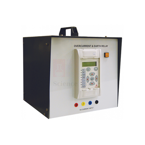
Overcurrent And Earth Fault Relay
Overcurrent And Earth Fault Relay (Product Code: SLE/EPS/01) is a programmable protection-relay module used to teach how overcurrent and earth-fault protection is set, tested and verified in power system and electrical engineering laboratories. It is based on the Micom P122 industrial relay and provides three independent three-phase overcurrent and earth-fault stages, the first selectable from 12 IDMT curves. It is supplied by Jain Scientific Equipments Pvt Ltd (ScienceLab), Ambala, India.
Specifications
| Parameter | Detail |
|---|---|
| Relay basis | Micom P122 industrial relay |
| Programming | Keypad and display on the relay module; or relay support software on a suitable computer |
| Three-phase earth and overcurrent | Three independent stages; first stage selectable from any of 12 IDMT curves; remaining stages with a direct time characteristic |
| Restricted earth fault | High impedance |
| Thermal protection | Thermal overload |
| Negative-phase sequence overcurrent | Two independent stages |
| Other functions | Broken conductor detection; selectable blocking; undercurrent; circuit monitoring |
| Records | Trend, fault and disturbance records |
| Test arrangement | Connected to fault circuits set up on a Protection and Relay Test Set; most tests use single relays |
| Product code | SLE/EPS/01 |
| Supplied by | Jain Scientific Equipments Pvt Ltd (ScienceLab), Ambala, India |
What Is the Overcurrent and Earth Fault Relay Used For?
Protection relays decide when a circuit breaker must trip, and setting them correctly is a core skill for power engineers. In the lab, the lecturer or students build a fault circuit on the Protection and Relay Test Set, program the relay module for the test using its keypad and display (or from a computer running the relay support software), and then apply the fault. Measuring how quickly the relay operates at different fault currents lets students plot its real characteristic and compare it with the selected IDMT curve.
Because the first stage offers 12 IDMT curves and the remaining stages have a direct time characteristic, one relay can show how the choice of curve changes tripping times and how separate stages are graded against each other. Further exercises cover restricted earth fault, thermal overload, negative-phase-sequence protection and broken conductor detection, while the stored fault and disturbance records let students review each event after the test.
What to Specify When Ordering
- Whether you already have a Protection and Relay Test Set or need a test arrangement discussed with us.
- Whether a computer and the relay support software should be arranged for programming.
- Other protection relays for the same lab, such as differential, distance or directional types.
- Number of relay modules for your student groups.
Supplier
Jain Scientific Equipments Private Limited, trading as ScienceLab, sources and supplies the Overcurrent And Earth Fault Relay module to electrical engineering colleges, polytechnics, power-sector training institutes, dealers and importers in India and international markets. It can be quoted together with other relay modules and power system trainers as a single laboratory package.
Company background is available on the ScienceLab profile.
Related Power & Energy Systems Trainers
A protection laboratory typically combines several relay types with switching equipment:
- Directional/Non-Directional Overcurrent Relay — adds direction sensing for ring and parallel feeders.
- Differential Protection Relay — unit protection for transformers and machines.
- Distance Protection Relay — impedance-based protection for transmission lines.
- Circuit Breaker Trainer — shows the switching device that a relay trips.
Explore all Power & Energy Systems Trainers.
Frequently Asked Questions
Which relay is the Overcurrent And Earth Fault Relay module based on?
The Overcurrent And Earth Fault Relay module is based on the Micom P122 industrial relay, so students set and test an industrial protection relay rather than a simplified teaching device.
How many IDMT curves does the Overcurrent And Earth Fault Relay offer?
The Overcurrent And Earth Fault Relay offers three independent three-phase earth and overcurrent stages. The first stage is selectable from any of 12 IDMT curves, and the remaining stages have a direct time characteristic.
How is the Overcurrent And Earth Fault Relay programmed?
The Overcurrent And Earth Fault Relay is programmed with the keypad and display on the relay module, or with the relay support software on a suitable computer. Settings are entered before each test on the fault circuits.
What else is needed to test the Overcurrent And Earth Fault Relay?
The Overcurrent And Earth Fault Relay is connected to fault circuits set up on a Protection and Relay Test Set, and most tests are performed with single relays. Ask us through the contact page about a suitable test arrangement.
Who supplies the Overcurrent And Earth Fault Relay?
The Overcurrent And Earth Fault Relay is supplied by Jain Scientific Equipments Pvt Ltd (ScienceLab), Ambala, Haryana, India, to engineering institutions, dealers and importers in India and international markets, alone or with other protection relays.
Is a calibration certificate available for the Overcurrent And Earth Fault Relay?
A calibration or test certificate for the Overcurrent And Earth Fault Relay module is not listed as standard. If your laboratory needs such documentation, please discuss it with us through the contact page before ordering.
Request a Quote
Send your requirement for the Overcurrent And Earth Fault Relay through the contact page or add it to the enquiry cart.
Last updated: 24 September 2026
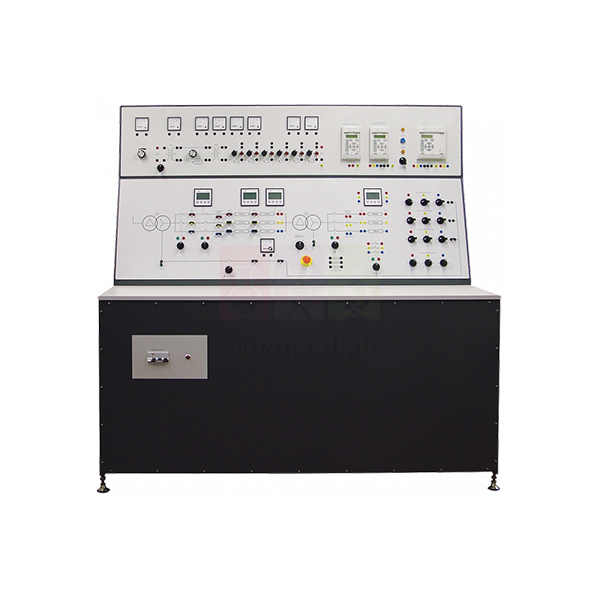
Distribution Trainer
Distribution Trainer (Product Code: SLE/EPS/02) is a two-panel electrical training system used to teach low-voltage and three-phase power distribution — feeders, loads, regulation, ring main and radial circuits — in power systems laboratories at engineering colleges, polytechnics and technical institutes. Its upper panel covers distribution basics with lamps and variable resistances, while its lower panel simulates industrial three-phase distribution using two three-phase transformers, one of which steps the line voltage down to 110 V. It is made by Jain Scientific Equipments Pvt Ltd (ScienceLab), an OEM manufacturer, at its own factory in Ambala, India.
Key Details
| Parameter | Detail |
|---|---|
| Upper panel | Basics of distribution: low-voltage AC and DC supplies, a set of lamps and variable resistances |
| Feeder and load simulation | Variable resistances simulate a feeder cable; lamps simulate loads |
| Lower panel | Advanced three-phase distribution: connections to two three-phase transformers, lines and loads to simulate industrial power distribution |
| Supply transformer | Reduces the incoming supply voltage to the correct value for the experiments |
| Line receive transformer | Reduces the line voltage down to 110 V |
| Transformer connections | Adjustable primary tappings; secondary winding star point can be connected to earth |
| Metering | All current, voltage and power meters needed for the experiments are on the panels |
| Experiments | Ring main and radial circuits; principles of regulation |
| Product code | SLE/EPS/02 |
| Manufacturer | Jain Scientific Equipments Pvt Ltd (ScienceLab) — OEM |
| Country of origin | India (made in Ambala, Haryana) |
What Is the Distribution Trainer Used For?
Students start on the upper panel, where a variable resistance stands in for a length of feeder cable and lamps act as consumer loads. Wiring the feeder as a radial circuit and then as a ring main shows why the ring keeps voltage higher at the far end and keeps supply going if one section is opened. Connecting the low-voltage AC supplies and changing load makes voltage regulation — the drop between no load and full load — something students can measure rather than just calculate.
The lower panel moves the same ideas to three-phase systems. One transformer brings the incoming supply down to the correct value for the experiments, lines carry power to the loads, and the second transformer reduces the line voltage to 110 V as the receiving-end transformer. Adjusting the primary tappings and earthing the secondary star point illustrates practical choices in real distribution networks, while the built-in current, voltage and power meters mean no extra instruments are needed for the core experiments.
What to Specify When Ordering
- Your incoming mains supply (voltage, phases and frequency), which is not stated in the listing.
- Bench or floor space for the two-panel trainer.
- Whether additional load banks or transformers are wanted for extended experiments.
- Number of trainers for your laboratory.
OEM Manufacturer
Jain Scientific Equipments Private Limited, whose trading name is ScienceLab, is the OEM of the Distribution Trainer. The trainer is made and assembled at the company's own licensed factory at 449, HSIIDC Industrial Area, Saha, Ambala, Haryana, India, and each trainer ships directly from there to the customer.
Electrical engineering departments, ITIs, dealers and importers therefore get quotations, technical guidance and any later spares or repeat units straight from the manufacturer — ask us for what you need. See our company profile.
Related Power & Energy Systems Trainers
These trainers extend distribution experiments into loading, transformation and system studies:
- Three-phase Mobile Transformer — a separate three-phase transformer for further network set-ups.
- Portable Resistive Load Bank — adds controllable resistive load to distribution circuits.
- Portable Inductive Load Bank — reactive loading to study its effect on voltage regulation.
- Modular Power System — broader generation-to-load power system experiments.
Browse all Power & Energy Systems Trainers.
Frequently Asked Questions
What does the Distribution Trainer teach?
The Distribution Trainer teaches the basics of power distribution on its upper panel and three-phase industrial distribution on its lower panel, including feeder and load simulation, ring main and radial circuits, and the principles of voltage regulation.
How are feeders and loads simulated on the Distribution Trainer?
On the Distribution Trainer's upper panel, variable resistances simulate a feeder cable and a set of lamps simulates consumer loads, supplied from low-voltage AC and DC sources, so students can see voltage drop and load sharing directly.
What transformers are used in the Distribution Trainer?
The Distribution Trainer's lower panel connects to two three-phase transformers. One reduces the incoming supply to the correct experimental value; the other reduces the line voltage to 110 V and acts as the line receive transformer.
Are meters included with the Distribution Trainer?
Yes. The Distribution Trainer panels include all the current, voltage and power meters needed for the experiments, so students can take readings without connecting separate instruments for the standard exercises.
Who manufactures the Distribution Trainer?
The Distribution Trainer is manufactured by Jain Scientific Equipments Pvt Ltd (ScienceLab), the OEM, at its own licensed factory in Saha, Ambala, Haryana, India, and supplied factory-direct to institutions, dealers and importers in India and international markets.
What should a quotation request for the Distribution Trainer include?
A quotation request for the Distribution Trainer should give your mains voltage and frequency, the number of trainers, any extra load banks or transformers wanted and the delivery address. Send it through the contact page.
Request a Quote
Quotes for the Distribution Trainer come direct from the manufacturer. Use the contact page or add the trainer to the enquiry cart.
Last updated: 24 September 2026
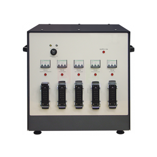
Modular Power System
Modular Power System (Product Code: SLE/EPS/03) is a power and interconnection hub used to join two or more power system training modules into one working setup in electrical engineering and technical training laboratories. Connected to a suitable mains supply, it powers each module, links their test circuits and ties every emergency stop into one safety network. It is made by Jain Scientific Equipments Pvt Ltd (ScienceLab), an OEM manufacturer, at its own factory in Ambala, India, within its engineering lab equipment in India range.
Key Details
| Parameter | Detail |
|---|---|
| Function | Hub needed to connect two or more modules of the Modular Power System together |
| Power distribution | Provides power for each part of the system when connected to a suitable mains supply |
| Test circuit linking | Links the electrical test circuits between modules, so long test leads between modules are not needed |
| Emergency stop linking | Links the emergency stop buttons of each connected module |
| Emergency stop settings | Two: stop power to the affected module only (others stay powered), or stop power to all modules |
| Setting selector | Keyswitch, to prevent unauthorised use |
| Product code | SLE/EPS/03 |
| Manufacturer | Jain Scientific Equipments Pvt Ltd (ScienceLab) — OEM |
| Country of origin | India (made in Ambala, Haryana) |
What Is the Modular Power System Used For?
The Modular Power System hub is used whenever students work on more than one power system module at the same time. Instead of running long test leads across the bench, the hub carries the electrical test circuits between modules, so wiring stays short and each experiment is quicker to set up and check. This suits electrical engineering, polytechnic and vocational training laboratories that teach how interconnected power networks behave.
Safety is its second job. Because every module’s emergency stop button is linked through the hub, the lecturer decides with the keyswitch whether a stop isolates only the module where the problem occurred — useful when other groups are mid-experiment — or shuts down every connected module at once. Keeping the key with the lecturer stops students from changing that setting.
What to Specify When Ordering
- How many modules you intend to connect to the hub (it is designed for two or more).
- The mains supply available in your laboratory, so suitability can be confirmed.
- Which power system modules you already own or plan to add, so the links between them can be checked.
- Quantity required, for example one hub per bench or per lab.
OEM Manufacturer
Jain Scientific Equipments Private Limited, trading as ScienceLab, is the OEM (original equipment manufacturer) of the Modular Power System. The hub is made and assembled at the company’s own licensed factory at 449, HSIIDC Industrial Area, Saha, Ambala, Haryana, not bought in from a trader, and is supplied factory-direct to engineering colleges, polytechnics, training institutes, dealers and importers.
The company is incorporated under CIN U29309HR2020PTC087597, and production runs under Factory Licence AMB-ONLINE-CHD-J-414. Replacement parts and repeat orders are handled by the manufacturer itself — just ask us. More about the company is on the ScienceLab company profile.
Related Power & Energy Systems Trainers
These trainers from the same range are typically set up alongside the Modular Power System on a power systems bench:
- Power System Simulator Generator — motor-generator set with relay-protected circuit-breakers for generation experiments.
- Distribution Trainer — for distribution-level network experiments.
- Power Factor Load Bank — resistive, inductive and capacitive loads for power factor tests.
- Circuit Breaker Trainer — fuses and circuit-breakers under controlled fault currents.
- Overcurrent And Earth Fault Relay — for protection relay experiments.
See the complete range of Power & Energy Systems Trainers, from protection relays and load banks to solar energy equipment.
Frequently Asked Questions
What does the Modular Power System do?
The Modular Power System (SLE/EPS/03) is the hub that joins two or more power system modules. Connected to a suitable mains supply, it powers each module, links their electrical test circuits and connects all their emergency stop buttons, so students need no long test leads between modules.
What emergency stop options does the Modular Power System offer?
The Modular Power System offers two emergency stop settings. One cuts power only to the module where the stop was pressed and leaves the other modules powered; the other cuts power to every connected module at once.
Why is the emergency stop setting selected with a keyswitch?
The Modular Power System uses a keyswitch for its emergency stop setting to prevent unauthorised use. Only the person holding the key, normally the lecturer or lab supervisor, can change whether a stop isolates one module or all connected modules.
Who manufactures the Modular Power System?
The Modular Power System is manufactured by Jain Scientific Equipments Pvt Ltd (ScienceLab), the OEM, at its own licensed factory in Saha, Ambala, Haryana, India. Quotations, repeat orders and spare-part enquiries are handled directly by the manufacturer.
What mains supply does the Modular Power System need?
The Modular Power System needs a suitable mains supply; the exact voltage and frequency are not listed on this page. State your laboratory’s supply when you enquire through our contact page and ScienceLab will confirm suitability before quoting.
Can the Modular Power System be supplied in bulk or for export?
Yes. Jain Scientific Equipments Pvt Ltd (ScienceLab) supplies the Modular Power System to institutions and dealers in India and international markets. For a quotation, give the quantity, the number of modules you plan to connect and your mains supply.
Request a Quote
To order the Modular Power System (SLE/EPS/03), send your requirement through our contact page or add it to the enquiry cart. Quotations come direct from the manufacturer, ScienceLab, Ambala, for single units, full lab setups and bulk orders.
Last updated: 24 September 2026
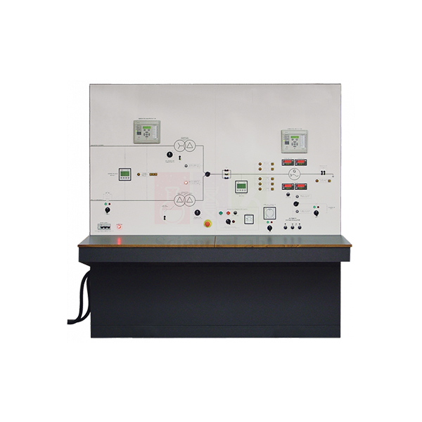
Power System Simulator Generator
Power System Simulator Generator (Product Code: SLE/EPS/04) is a motor-driven generator console used to simulate a central power station feeding a transmission network in power systems laboratories. Electrical engineering students and trainees use it to study excitation control, prime mover speed and generator protection, with relays that operate real circuit-breakers — a core item of lab equipment for technical institutes. It is built by Jain Scientific Equipments Pvt Ltd (ScienceLab), an OEM manufacturer, at its own factory in Ambala, India.
Key Details
| Parameter | Detail |
|---|---|
| Machine set | Motor and generator set: two coupled machines mounted in the base of the control console |
| Motor speed control | Vector drive |
| Generator output control | Manual excitation or different types of automatic excitation |
| Metering | Digital meters showing the conditions of the prime mover and generator |
| Circuit-breakers | Include hand-operated switches and lamps that show whether each breaker is open or closed |
| Protection relays | Set by students from their control panels; operate the circuit-breakers around the second generator |
| Computer link | Relay sockets for connection to a suitable computer for more detailed programming, if needed |
| System connection | Links to the Power System Trainer at the higher voltage (transmission) level to simulate central generation |
| Product code | SLE/EPS/04 |
| Manufacturer | Jain Scientific Equipments Pvt Ltd (ScienceLab) — OEM |
| Country of origin | India (made in Ambala, Haryana) |
What Is the Power System Simulator Generator Used For?
The simulator represents a second generating source — the kind of large central station, such as a main power station, that feeds the grid at transmission voltage. Linked to the Power System Trainer at that level, it lets students compare manual and automatic excitation control of generator output, vary motor speed through the vector drive and read prime mover and generator conditions on the digital meters.
Protection is the second half of the syllabus it supports. Students set the relays from their control panels, create the conditions that make a relay trip the circuit-breakers around the generator, and confirm the result from the breaker lamps. This shows how actual generators are protected and why different protection methods exist. For deeper work, the relays can be linked to a suitable computer for more detailed programming.
What to Specify When Ordering
- Whether you already have the Power System Trainer that the simulator links to at transmission level, or need both.
- Whether relay programming from a computer is planned, so the computer link can be discussed.
- The mains supply available in your laboratory.
- Quantity and delivery location (within India or export).
OEM Manufacturer
ScienceLab, the trading name of Jain Scientific Equipments Private Limited, is the OEM (original equipment manufacturer) of the Power System Simulator Generator. The console is made and assembled at the company’s own licensed factory in Saha, Ambala, Haryana, India, and dispatched factory-direct to universities, polytechnics, TVET lab equipment buyers, dealers and importers.
Because you deal with the manufacturer, questions about the relays, meters or replacement parts go straight to the people who build the unit — ask us. Company background is on the ScienceLab profile page.
Related Power & Energy Systems Trainers
Items often combined with the Power System Simulator Generator in a power systems lab:
- Modular Power System — hub that powers modules and links their test circuits and emergency stops.
- Power Factor Load Bank — predictable resistive, inductive and capacitive loads for power systems experiments.
- Overcurrent And Earth Fault Relay — further protection relay studies.
- Differential Protection Relay — three-phase differential protection characteristics.
- Three-phase Mobile Transformer — transformer theory and three-phase connections.
Explore more Power & Energy Systems Trainers for generation, protection and load studies.
Frequently Asked Questions
What is the Power System Simulator Generator?
The Power System Simulator Generator (SLE/EPS/04) is a control console with two coupled machines, a motor and a generator, mounted in its base. It links to the Power System Trainer at transmission level to simulate central generation, such as a main power station.
How is the generator output controlled?
On the Power System Simulator Generator, generator output is controlled by manual excitation or by different types of automatic excitation, while a vector drive controls the speed of the driving motor. Digital meters show the prime mover and generator conditions throughout the test.
How does the Power System Simulator Generator teach generator protection?
Students set its relays from their control panels. The relays operate the circuit-breakers around the second generator, and lamps show whether each breaker is open or closed, demonstrating how actual generators are protected and the different ways they are protected.
Can the relays be programmed from a computer?
Yes. The relays on the Power System Simulator Generator include sockets for linking to a suitable computer for more detailed programming, if needed. Ask ScienceLab through the contact page about the connection details before you order.
Who manufactures the Power System Simulator Generator?
Jain Scientific Equipments Pvt Ltd (ScienceLab) manufactures the Power System Simulator Generator as the OEM at its own licensed factory in Saha, Ambala, Haryana, India. Buyers deal directly with the manufacturer for quotations, repeat orders and spare-part enquiries.
What should a quotation request include?
For a Power System Simulator Generator quotation, tell ScienceLab the quantity, your mains supply, whether you also need the Power System Trainer it links to, and whether computer programming of the relays is planned. Supply covers India and international markets.
Request a Quote
Send your Power System Simulator Generator (SLE/EPS/04) enquiry through the contact page or place it in the enquiry cart. Prices are quoted direct by the manufacturer, with no trader in between.
Last updated: 24 September 2026
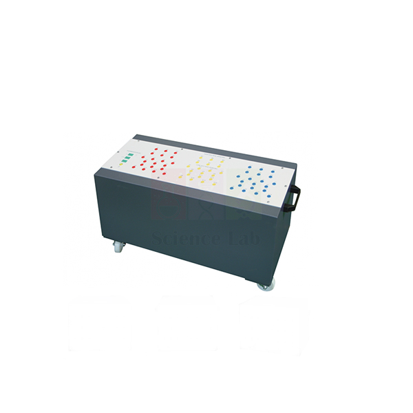
Three-phase Mobile Transformer
Three-phase Mobile Transformer (Product Code: SLE/EPS/05) is a three-limb, three-phase teaching transformer used to demonstrate transformer theory and winding connections in electrical engineering and polytechnic laboratories. Its windings work at one volt per turn, so the no-load secondary voltage equals the number of secondary turns — something students can check for themselves. It is produced by Jain Scientific Equipments Pvt Ltd (ScienceLab), an OEM and technical educational equipment manufacturer, at its own factory in Ambala, India.
Specifications
| Parameter | Detail |
|---|---|
| Construction | Three identical transformers on a common core, forming a three-limb, three-phase transformer |
| Volts per turn | One volt each turn (no-load output voltage equals the number of secondary turns) |
| Tappings | Selection of high-voltage (primary) and low-voltage (secondary) tappings for a range of input and output voltages |
| Terminals | All tappings connected to coloured, shrouded sockets for safety |
| Winding connections | All tappings accessible, so windings can be linked to suit any of the common three-phase connections |
| Enclosure | Steel enclosure with small wheels for ease of mobility |
| Product code | SLE/EPS/05 |
| Manufacturer | Jain Scientific Equipments Pvt Ltd (ScienceLab) — OEM |
| Country of origin | India (made in Ambala, Haryana) |
What Is the Three-phase Transformer Used For?
Students use the Three-phase Mobile Transformer to explore transformer principles with values they can predict. Because each turn produces one volt, the expected no-load output of any secondary tapping is simply its turn count, so turns-ratio and voltage-ratio exercises are quick to verify with a meter.
With every tapping on its own shrouded socket, groups wire the primary and secondary windings to suit the experiment — including the common three-phase connections such as star and delta — and compare line and phase voltages. The wheeled steel enclosure lets one unit move between benches, or into a lecture room for demonstrations. Always isolate the supply before changing connections.
What to Specify When Ordering
- The input (primary) and output (secondary) voltages your experiments need, so the tapping selection can be confirmed.
- The three-phase supply available in your laboratory.
- Number of units: one per student group, or one for lecture demonstrations.
OEM Manufacturer
Jain Scientific Equipments Private Limited, which trades as ScienceLab, is the OEM (original equipment manufacturer) of the Three-phase Mobile Transformer. Each unit is made at the company’s own licensed factory in Saha, Ambala, Haryana, India, and sold factory-direct, so colleges, training centres, dealers and importers get quotations and after-sales answers from the maker rather than a middleman.
Need a replacement part or a matching unit for another bench later? Ask us — repeat orders are handled by the manufacturer. Read more on the ScienceLab company profile.
Related Power & Energy Systems Trainers
Useful companions for transformer and three-phase circuit experiments:
- Portable Resistive Load Bank — star or delta resistive loads for loading three-phase circuits.
- Portable Inductive Load Bank — switchable inductive loads, balanced or unbalanced.
- Power System Simulator Generator — simulated central generation for wider power system studies.
- Digital Multimeter — for reading winding and line voltages.
The full Power & Energy Systems Trainers range covers transformers, load banks, relays and renewable energy equipment.
Frequently Asked Questions
Why does the Three-phase Mobile Transformer work at one volt per turn?
The Three-phase Mobile Transformer is wound at one volt per turn so that its no-load output voltage equals the number of turns on the secondary. Students can predict output voltages from turn counts and check transformer principles clearly.
Which three-phase connections can students make?
All tappings of the Three-phase Mobile Transformer are accessible, so students can link the primary and secondary windings to suit any of the common three-phase connections. Each tapping ends in a coloured, shrouded socket, keeping the wiring clear and safer.
How is the Three-phase Mobile Transformer built?
The Three-phase Mobile Transformer uses three identical transformers on a common core, forming a three-limb, three-phase transformer. It sits inside a steel enclosure with small wheels, so it moves easily between benches or rooms.
Can it give different input and output voltages?
Yes. The Three-phase Mobile Transformer has a selection of high-voltage (primary) and low-voltage (secondary) tappings for a range of input and output voltages. Share the voltages you need through our contact page so we can confirm suitability.
Who manufactures the Three-phase Mobile Transformer?
The Three-phase Mobile Transformer is manufactured by Jain Scientific Equipments Pvt Ltd (ScienceLab), the OEM, at its own factory in Saha, Ambala, Haryana, India. Orders, spare parts and technical questions are handled by the manufacturer itself.
Is the transformer available for export?
Yes. ScienceLab supplies the Three-phase Mobile Transformer to colleges, institutes and dealers in India and international markets. A quotation request should give the quantity, your three-phase supply and the input and output voltages you plan to use.
Request a Quote
Ask for a Three-phase Mobile Transformer (SLE/EPS/05) quotation through the contact page, or add the item to your enquiry cart with other lab equipment. Your quote comes straight from the manufacturer in Ambala.
Last updated: 24 September 2026
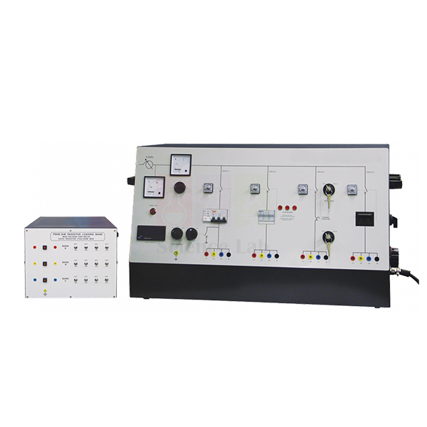
Circuit Breaker Trainer
Circuit Breaker Trainer (Product Code: SLE/EPS/06) is a protection-device trainer used to test and compare fuses and circuit-breakers under controlled fault currents in electrical engineering, polytechnic and electrician training labs. Its four circuits each carry a different protective device, and an internal variable transformer sets the fault current in each one. It is made by Jain Scientific Equipments Pvt Ltd (ScienceLab), an OEM manufacturer, at its own factory in Ambala, India.
Key Details
| Parameter | Detail |
|---|---|
| Test circuits | Four, each with a different current protection device |
| Protection devices | Fuses, magnetic-only circuit-breaker, thermal-only circuit-breaker and thermomagnetic circuit-breaker |
| Fault current control | Variable transformer inside the unit works with the load to set and control the fault current in each circuit |
| Circuit one | Additional adjustable residual current detector for experiments with different residual current faults |
| Circuit two | Tests fuses; ‘fuse break’ detector circuit with lamps showing when each fuse breaks |
| Circuit three | Remote and local control keyswitches to switch its contact breaker and break the circuit |
| Switching | Each circuit has a contact breaker switched by an industrial standard discrepancy switch |
| Earth leakage setting | Digital display and switches to set the earth leakage fault current before the test |
| Product code | SLE/EPS/06 |
| Manufacturer | Jain Scientific Equipments Pvt Ltd (ScienceLab) — OEM |
| Country of origin | India (made in Ambala, Haryana) |
What Is the Circuit Breaker Trainer Used For?
The trainer answers a question every electrician and power engineer must understand: how quickly does each protective device clear a given fault current? Students set a fault current, apply it and note the breaking time, building up the fault current and breaking time relationship for different fuse types and comparing it with magnetic, thermal and thermomagnetic breakers.
It also covers earth leakage and switching practice. On circuit one, students set the earth leakage fault current on the digital display and try the adjustable residual current detector against different residual current faults. Circuit three’s local and remote keyswitches show how a control room operator or a remote operator switches a circuit on or off in a real installation — which makes this useful vocational training lab equipment for electrician courses.
What to Specify When Ordering
- The mains supply available in your laboratory.
- The fuse types you want students to compare.
- Whether you need replacement fuses for repeated tests — ask us about availability.
- Number of trainers, for example one per student group.
OEM Manufacturer
ScienceLab is the trade name of Jain Scientific Equipments Private Limited, the OEM (original equipment manufacturer) that builds the Circuit Breaker Trainer at its own licensed factory in Saha, Ambala, Haryana, India. Colleges, training institutes, dealers and importers buy direct from the factory rather than through a trader.
That gives you manufacturer quotations and one point of contact for spares and repeat orders — ask us whenever you need them. Company details are on the ScienceLab profile.
Related Power & Energy Systems Trainers
Pair the Circuit Breaker Trainer with these items to extend protection studies:
- Overcurrent And Earth Fault Relay — relay-based overcurrent and earth fault protection to compare with fuses and breakers.
- Directional/Non-Directional Overcurrent Relay — IDMT overcurrent curves for time-grading exercises.
- Power System Simulator Generator — relays operating circuit-breakers around a generator.
- Digital Multimeter — for checking circuits and fuses between tests.
Browse all Power & Energy Systems Trainers for further protection and power systems equipment.
Frequently Asked Questions
What protection devices does the Circuit Breaker Trainer include?
The Circuit Breaker Trainer (SLE/EPS/06) has four circuits, each with a different current protection device: fuses, a magnetic-only circuit-breaker, a thermal-only circuit-breaker and a thermomagnetic circuit-breaker, so students can compare how each reacts to fault current.
How is the fault current set on the Circuit Breaker Trainer?
In the Circuit Breaker Trainer, a variable transformer inside the unit works with the load to set and control the fault current in each of the four circuits. A digital display and switches help set the earth leakage fault current before a test.
How do students see when a fuse breaks?
Circuit two of the Circuit Breaker Trainer tests fuses and includes a fuse break detector circuit with lamps that show students when each fuse breaks. This helps them plot the fault current and breaking time relationship for different fuse types.
Can the trainer demonstrate residual current faults and remote switching?
Yes. Circuit one of the Circuit Breaker Trainer has an adjustable residual current detector for different residual current faults, and circuit three has local and remote control keyswitches that show how control-room and remote operators switch circuits.
Who manufactures the Circuit Breaker Trainer?
Jain Scientific Equipments Pvt Ltd (ScienceLab) is the OEM that manufactures the Circuit Breaker Trainer at its own licensed factory in Saha, Ambala, Haryana, India. Buying direct means quotations, repeat units and spare-part requests are answered by the maker.
Is a calibration certificate available for the digital display?
Calibration-certificate availability for the Circuit Breaker Trainer’s digital display should be discussed with ScienceLab before ordering. Raise it on our contact page together with your quantity and mains supply, and we will advise what can be provided.
Request a Quote
For Circuit Breaker Trainer (SLE/EPS/06) pricing, write to us via the contact page or use the enquiry cart. The quotation is issued directly by the manufacturer for supply across India and international markets.
Last updated: 24 September 2026
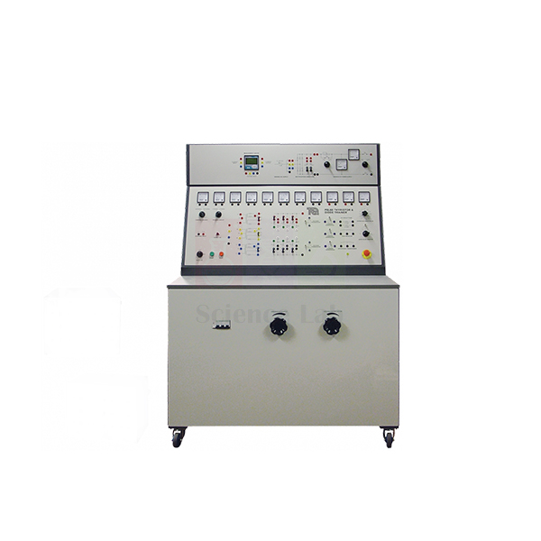
Thyristor and Diode Converters
Thyristor and Diode Converters (Product Code: SLE/EPS/07) is a power electronics trainer used to build and study diode and thyristor rectifier circuits in electrical and electronics engineering laboratories. Students patch thyristors, diodes, inductors, transformers and smoothing capacitors together on a mimic-diagram panel, then compare gate pulses with output waveforms on the oscilloscope included with the set. It is manufactured by Jain Scientific Equipments Pvt Ltd (ScienceLab), an OEM, at its own factory in Ambala, India.
Key Details
| Parameter | Detail |
|---|---|
| Control panel | Clear mimic diagrams with shrouded sockets; circuit parts connected with shrouded leads |
| Circuit components | Thyristors, diodes, inductors, transformers and smoothing capacitors |
| AC supply options | Multi-tapped transformers giving a choice of single-phase and three-phase AC voltages |
| Load inductor | Shows the effect of inductance when smoothing AC ripple in rectifier circuits |
| Interphase transformer | Centre-tapped; shows the effect of reducing circulating currents in rectifier circuits |
| Circuit protection | Fast-blow fuses on the control panel protect the load side of experiment circuits |
| Metering | Standard analogue meters plus a multi-function digital meter for currents and voltages |
| Lower panel controls | Adjust AC supply voltage and ballast resistance during experiments |
| Gate triggering | External or internal source selectable for the thyristor gates |
| Waveform viewing | Transducers for connecting the oscilloscope to compare gate pulses with output waveforms |
| Included | Oscilloscope |
| Product code | SLE/EPS/07 |
| Manufacturer | Jain Scientific Equipments Pvt Ltd (ScienceLab) — OEM |
| Country of origin | India (made in Ambala, Haryana) |
What Are Thyristor and Diode Converters Used For?
This trainer teaches how AC is converted to DC — first with uncontrolled diode rectifiers, then with thyristor circuits whose output depends on when the gates are triggered. Students select single-phase or three-phase AC from the multi-tapped transformers, wire each rectifier circuit on the mimic panel, and measure currents and voltages on the analogue meters and the multi-function digital meter.
Two parts make classic effects visible: the load inductor shows how inductance smooths AC ripple, and the centre-tapped interphase transformer shows how circulating currents in rectifier circuits are reduced. Through the transducers, the included oscilloscope displays gate pulses beside the output waveform, whether triggering comes from the internal or an external source. A good habit is to start each new circuit at a low AC supply voltage, set on the lower panel, and raise it once the wiring is checked.
What to Specify When Ordering
- The single-phase and three-phase mains supply available in your laboratory.
- Number of trainers needed for your student groups.
- Whether you need extra shrouded leads or replacement fast-blow fuses — ask us.
OEM Manufacturer
Jain Scientific Equipments Private Limited, known by its brand ScienceLab, is the OEM (original equipment manufacturer) of the Thyristor and Diode Converters trainer, which is built and assembled at its own licensed factory in Saha, Ambala, Haryana, India. The company is a registered MSME enterprise (Udyam UDYAM-HR-01-0003714), and export shipments are handled under Importer-Exporter Code AAECJ8618A (DGFT).
As an engineering lab equipment manufacturer selling factory-direct, ScienceLab quotes universities, polytechnics, dealers and importers without a trading middleman and handles spares enquiries itself. See the ScienceLab company profile for more.
Related Power & Energy Systems Trainers
Instruments and trainers that complement power electronics work on this unit:
- Oscilloscope Dual Trace — an extra waveform-viewing station for larger classes.
- Digital Multimeter — independent voltage and current checks at the bench.
- Three-phase Mobile Transformer — transformer theory and three-phase winding connections.
- Circuit Breaker Trainer — fuse and circuit-breaker behaviour under fault currents.
View the full range of Power & Energy Systems Trainers for more power engineering equipment.
Frequently Asked Questions
What components are on the Thyristor and Diode Converters trainer?
The Thyristor and Diode Converters trainer (SLE/EPS/07) provides thyristors, diodes, inductors, transformers and smoothing capacitors on a control panel with clear mimic diagrams and shrouded sockets. Students connect them with shrouded leads to build different rectifier circuits.
Is an oscilloscope included with the Thyristor and Diode Converters?
Yes. An oscilloscope is included with the Thyristor and Diode Converters trainer. Transducers let students connect it to show and compare the thyristor gate pulses with the output waveforms of the circuits they build.
Which AC supplies can the circuits use?
Multi-tapped transformers in the Thyristor and Diode Converters trainer give a choice of single-phase and three-phase AC voltages for connection to the diodes and thyristors. Controls on the lower panel adjust the AC supply voltage and ballast resistance during experiments.
How are the thyristor gates triggered?
For thyristor experiments on the Thyristor and Diode Converters trainer, students select either an internal or an external source to trigger the thyristor gates, then compare the gate pulses with the output waveform on the included oscilloscope.
How are the experiment circuits protected?
Fast-blow fuses on the control panel of the Thyristor and Diode Converters trainer protect the load side of experiment circuits, and all connections use shrouded sockets and leads. Ask ScienceLab about replacement fuses when you order.
Who manufactures the Thyristor and Diode Converters trainer?
The Thyristor and Diode Converters trainer is manufactured by Jain Scientific Equipments Pvt Ltd (ScienceLab), the OEM, at its own licensed factory in Saha, Ambala, Haryana, India, and supplied factory-direct to institutions and dealers in India and international markets.
Can a calibration certificate be supplied for the meters?
Whether a calibration certificate can be supplied for the meters of the Thyristor and Diode Converters trainer should be discussed with ScienceLab before you order. Mention it on our contact page with your quantity and supply details.
Request a Quote
Request a Thyristor and Diode Converters (SLE/EPS/07) quotation through the contact page or add it to the enquiry cart. You receive the quote directly from the manufacturer, ScienceLab, Ambala.
Last updated: 24 September 2026
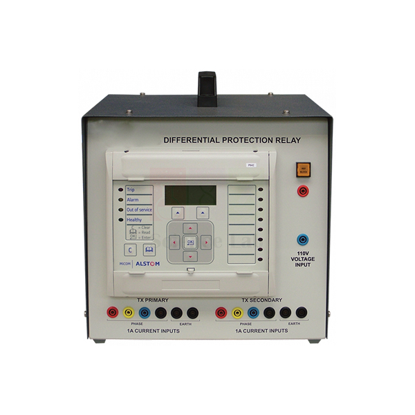
Differential Protection Relay
Differential Protection Relay (Product Code: SLE/EPS/08) is a desk-mounted relay module used to demonstrate the characteristics of three-phase differential protection in power system protection laboratories. Built around a Micom industrial relay in a robust enclosure with a carrying handle, it lets lecturers and students program real relay settings and test them against fault circuits. It is supplied by Jain Scientific Equipments Pvt Ltd (ScienceLab), Ambala, India, a laboratory instruments supplier in India for engineering colleges.
Specifications
| Parameter | Detail |
|---|---|
| Purpose | Clearly shows the characteristics of three-phase differential protection |
| Relay | A Micom industrial relay forms the main part of the unit |
| Enclosure | Robust enclosure with carrying handle |
| Mounting | On the desk area of the Protection and Relay Test Set or other Power System product |
| System connection | Multi-core cable from the back of the relay to the Power System product |
| Test connections | 4 mm shrouded sockets to the test circuits |
| Programming | Keypad and display on the relay module, or Micom S1 software on a suitable computer |
| Product code | SLE/EPS/08 |
| Supplied by | Jain Scientific Equipments Pvt Ltd (ScienceLab), Ambala, India |
What Is the Differential Protection Relay Used For?
Differential protection compares the current entering and leaving a protected zone, such as a transformer or generator winding, and trips when the two no longer balance. This module lets students see that principle on real hardware: fault circuits are set up on the Protection and Relay Test Set or another Power System product, and the relay’s response reveals the three-phase differential characteristic.
A typical session runs in three steps. First, mount the unit on the desk area and connect the multi-core cable from the back of the relay. Next, program the settings with the keypad and display, or from a suitable computer running Micom S1 software. Finally, link the 4 mm shrouded sockets to the test circuits and apply faults inside and outside the protected zone to compare the outcome.
What to Specify When Ordering
- The Protection and Relay Test Set or other Power System product the relay will mount on and connect to.
- Whether you plan to program it from a computer with Micom S1 software.
- Number of relay modules required.
Supplier
ScienceLab is the trading name of Jain Scientific Equipments Private Limited, based in Ambala, Haryana, India. The company supplies the Differential Protection Relay to engineering colleges, polytechnics and training institutes alongside the power systems trainers it is used with, for delivery in India and international markets.
Because the core of the unit is a Micom industrial relay, raise any questions about the relay model or the Micom S1 software when you enquire. More about the company is on the ScienceLab profile.
Related Power & Energy Systems Trainers
Other protection items used in the same relay-testing workflow:
- Distance Protection Relay — Micom-based module for phase and ground distance protection.
- Directional/Non-Directional Overcurrent Relay — overcurrent, earth fault and voltage functions.
- Overcurrent And Earth Fault Relay — a further relay for protection experiments.
- Power System Simulator Generator — generator console with relay-operated circuit-breakers.
Find more in our Power & Energy Systems Trainers category.
Frequently Asked Questions
What does the Differential Protection Relay demonstrate?
The Differential Protection Relay (SLE/EPS/08) clearly shows the characteristics of three-phase differential protection. Students program it, connect it to fault circuits on the Protection and Relay Test Set or another Power System product, and observe how the relay responds.
Which relay is inside the Differential Protection Relay unit?
A Micom industrial relay forms the main part of the Differential Protection Relay, so students work with a real industrial relay’s keypad, display and settings. The relay is housed in a robust enclosure with a carrying handle.
How is the Differential Protection Relay programmed?
The Differential Protection Relay is programmed with the keypad and display on the relay module, or with Micom S1 software on a suitable computer. The lecturer or student enters the settings needed for each test before connecting to the fault circuits.
How does the relay connect to the test equipment?
The Differential Protection Relay mounts on the desk area of the Protection and Relay Test Set or another Power System product. A multi-core cable runs from the back of the relay to that product, and 4 mm shrouded sockets link the relay to the test circuits.
Who supplies the Differential Protection Relay?
The Differential Protection Relay is supplied by Jain Scientific Equipments Pvt Ltd (ScienceLab), Ambala, Haryana, India, to colleges, institutes and dealers in India and international markets. Its core component is a Micom industrial relay.
What does a quotation request need?
To quote the Differential Protection Relay, ScienceLab needs the quantity, the Protection and Relay Test Set or Power System product it will be used with, and whether computer programming with Micom S1 software is planned. Send these through our contact page.
Request a Quote
Enquire about the Differential Protection Relay (SLE/EPS/08) on our contact page, or add it to the enquiry cart together with the trainers you plan to use it with.
Last updated: 24 September 2026
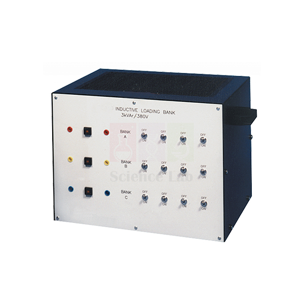
Portable Inductive Load Bank
Portable Inductive Load Bank (Product Code: SLE/EPS/09) is a switchable inductive load used to apply reactive, lagging-power-factor loads to three-phase experiment circuits in power systems laboratories. Its three electrically separate inductor banks, housed in a robust steel enclosure, connect in star or delta and switch to give balanced or unbalanced loads. It is manufactured by Jain Scientific Equipments Pvt Ltd (ScienceLab), an OEM and laboratory equipment manufacturer in India, at its own factory in Ambala.
Key Details
| Parameter | Detail |
|---|---|
| Enclosure | Robust steel enclosure |
| Load banks | Three banks of switchable inductive loads |
| Bank isolation | Each bank electrically separate, for star or delta connection in three-phase circuits |
| Switching | Set of switches to bring each inductor into circuit |
| Load conditions | Balanced or unbalanced inductive loads |
| Protection | Thermally operated circuit-breaker protecting the inductors |
| Connections | Safety sockets on the enclosure front panel |
| Combined use | Works with other similar load banks to provide variable power and power factor loads |
| Product code | SLE/EPS/09 |
| Manufacturer | Jain Scientific Equipments Pvt Ltd (ScienceLab) — OEM |
| Country of origin | India (made in Ambala, Haryana) |
What Is the Inductive Load Bank Used For?
An inductive load draws current that lags the voltage, so this unit is how students create reactive power and a lagging power factor in a controlled, repeatable way. Switching inductors into each bank, they load a generator, transformer or distribution circuit and watch how current, voltage and power factor respond.
Because the three banks are electrically separate, the same load bank serves both star-connected and delta-connected experiments, and different switch settings per bank produce the unbalanced loads needed to study phase imbalance. Paired with a resistive load bank, it forms a mixed resistive-inductive load whose power factor can be stepped up or down during a practical.
What to Specify When Ordering
- The voltage and current of the circuits it will load, so suitability can be confirmed (ratings are not listed on this page).
- Whether you also need the resistive or power factor load bank for combined-load experiments.
- Number of units per laboratory.
OEM Manufacturer
The Portable Inductive Load Bank is an Ambala-made product: ScienceLab, the brand of Jain Scientific Equipments Private Limited, is its OEM (original equipment manufacturer) and makes and assembles it at the company’s own licensed factory in Saha, Ambala, Haryana, India. It is sold factory-direct to engineering colleges, polytechnics, dealers and importers.
For spare parts or matching units for additional benches, ask us — the manufacturer handles repeat orders itself. Learn more on the ScienceLab company profile.
Related Power & Energy Systems Trainers
Loads and sources that work alongside the inductive load bank:
- Portable Resistive Load Bank — resistive counterpart for combined resistive-inductive loads.
- Power Factor Load Bank — resistive, inductive and capacitive banks in one mobile unit.
- Three-phase Mobile Transformer — a three-phase transformer to load in star or delta.
- Power System Simulator Generator — generator console for loading experiments.
More load banks, relays and trainers are listed under Power & Energy Systems Trainers.
Frequently Asked Questions
What is inside the Portable Inductive Load Bank?
The Portable Inductive Load Bank (SLE/EPS/09) is a robust steel enclosure containing three banks of switchable inductive loads. A set of switches brings each inductor into circuit, and safety sockets on the front panel connect the loads to experiment circuits.
Can the Portable Inductive Load Bank be connected in star or delta?
Yes. Each inductor bank in the Portable Inductive Load Bank is electrically separate, so the three banks can be connected as a star or a delta load for three-phase circuits, with balanced or unbalanced switch settings.
How are the inductors protected?
The inductors in the Portable Inductive Load Bank include a thermally operated circuit-breaker that protects the loads. If it operates during a practical, check the connected circuit and the switch settings before continuing the experiment.
Can it be combined with other load banks?
Yes. The Portable Inductive Load Bank can be used in combination with other similar load banks, such as the resistive version, to provide variable power and power factor loads for power systems experiments.
Who manufactures the Portable Inductive Load Bank?
The Portable Inductive Load Bank is manufactured by Jain Scientific Equipments Pvt Ltd (ScienceLab), the OEM, at its own licensed factory in Saha, Ambala, Haryana, India. Quotations and spare-part requests are answered straight from the manufacturer.
What inductance and current ratings does it have?
The inductance and current ratings of the Portable Inductive Load Bank are not listed on this page. Share your circuit voltage and required load through our contact page, and ScienceLab will confirm whether the unit suits your experiments.
Request a Quote
Get a Portable Inductive Load Bank (SLE/EPS/09) quotation from the manufacturer through our contact page, or collect it with other items in the enquiry cart. Supply is available across India and to international buyers.
Last updated: 24 September 2026
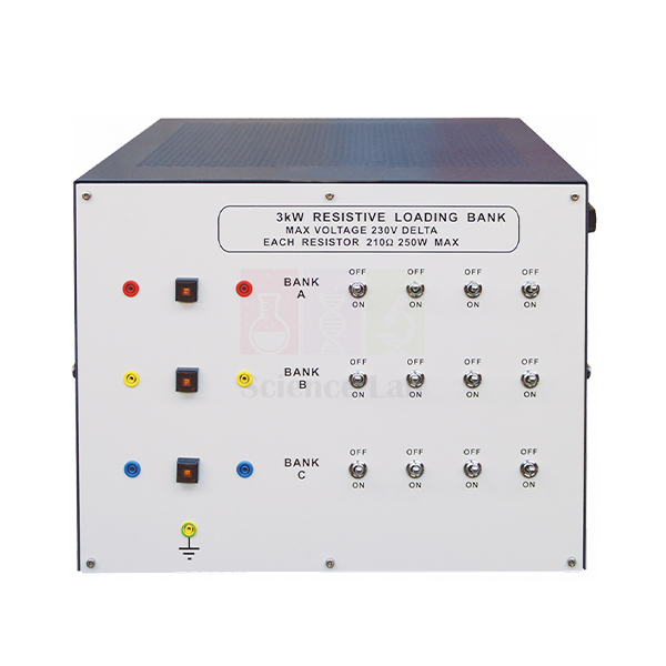
Portable Resistive Load Bank
Portable Resistive Load Bank (Product Code: SLE/EPS/10) is a three-phase resistive load used to draw controlled real power from generators, transformers and supply circuits during power systems practicals. Each of its three resistor banks is electrically separate and carries its own thermal circuit-breaker, so students can build balanced or unbalanced star or delta loads. It is made by Jain Scientific Equipments Pvt Ltd (ScienceLab), an OEM, at its own factory in Ambala, India, within its engineering educational equipment in India range.
Key Details
| Parameter | Detail |
|---|---|
| Load type | Resistive, in three switchable banks |
| Housing | Robust steel enclosure |
| Three-phase connection | Banks electrically separate, so they connect as a star or delta load |
| Resistor switching | Each bank has a set of switches to bring each resistor into circuit |
| Overload protection | Thermally operated circuit-breaker in each bank of resistors |
| Terminals | Safety sockets on the enclosure front panel |
| Load conditions | Balanced or unbalanced resistive loads |
| Expansion | Combine with other similar load banks for variable power and power factor loads |
| Product code | SLE/EPS/10 |
| Manufacturer | Jain Scientific Equipments Pvt Ltd (ScienceLab) — OEM |
| Country of origin | India (made in Ambala, Haryana) |
What Is the Resistive Load Bank Used For?
A resistive load takes current in phase with the voltage, so it absorbs real power at unity power factor and turns it into heat. That makes this unit the reference load in most power practicals: students add load resistor by resistor and record how a source’s terminal voltage, current and output change as demand rises.
Switch the three banks to different settings to create unbalanced conditions, or connect them in star or delta to compare line and phase quantities. When a non-unity power factor is needed, the resistive banks are combined with other similar load banks. Allow pauses between heavy load steps — the resistors run warm, and each bank’s thermal circuit-breaker is there to protect them.
What to Specify When Ordering
- Your supply voltage and the power you expect to dissipate, so suitability can be checked (ratings are not listed on this page).
- Any companion loads you need, such as the inductive or power factor load bank.
- Number of units for your benches.
OEM Manufacturer
Jain Scientific Equipments Private Limited, trading as ScienceLab, is the OEM (original equipment manufacturer) of the Portable Resistive Load Bank. Rather than reselling a trader’s stock, the company makes and assembles each unit at its own licensed factory at Saha, Ambala, Haryana, India, and supplies it factory-direct to institutions, dealers and importers.
Quotations come straight from the manufacturer, and spare parts can be requested directly — just ask us. Company information is on the ScienceLab profile page.
Related Power & Energy Systems Trainers
Equipment commonly used with a resistive load bank in power systems practicals:
- Portable Inductive Load Bank — adds a lagging reactive load for power factor studies.
- Power Factor Load Bank — free-standing unit with resistive, inductive and capacitive banks.
- Power System Simulator Generator — a generator source to load and protect.
- Modular Power System — hub linking module power, test circuits and emergency stops.
Compare all Power & Energy Systems Trainers to plan a complete power lab.
Frequently Asked Questions
What does the Portable Resistive Load Bank contain?
The Portable Resistive Load Bank (SLE/EPS/10) is a robust steel enclosure with three banks of switchable resistive loads. Each bank has a set of switches to bring each resistor into circuit, and safety sockets on the front panel connect it to experiment circuits.
Can the Portable Resistive Load Bank create unbalanced loads?
Yes. Because each bank of the Portable Resistive Load Bank is electrically separate and switched independently, students can create balanced or unbalanced resistive loads, connected as a star or a delta load for three-phase circuits.
How is the Portable Resistive Load Bank protected?
Each bank of resistors in the Portable Resistive Load Bank includes its own thermally operated circuit-breaker to protect the loads, and all connections to experiment circuits are made through safety sockets on the enclosure front panel.
Can it be used for power factor experiments?
Yes. The Portable Resistive Load Bank can be used with other similar load banks, for example the inductive load bank, to provide variable power and power factor loads. On its own it presents a purely resistive, unity power factor load.
Who manufactures the Portable Resistive Load Bank?
Jain Scientific Equipments Pvt Ltd (ScienceLab) manufactures the Portable Resistive Load Bank as the OEM at its own licensed factory in Saha, Ambala, Haryana, India, and supplies institutions and dealers across India and international markets directly.
What are the resistance values and power rating?
Resistance values and the power rating of the Portable Resistive Load Bank are not published on this page. Tell ScienceLab your supply voltage and required load through the contact page, and we will confirm suitability before quoting.
Request a Quote
Ask for Portable Resistive Load Bank (SLE/EPS/10) pricing on the contact page or add it to the enquiry cart. The manufacturer replies with a quotation for single units or complete power lab packages.
Last updated: 24 September 2026
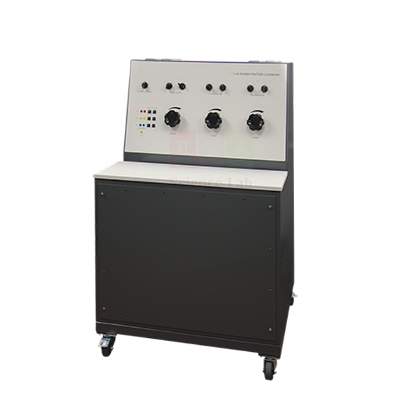
Power Factor Load Bank
Power Factor Load Bank (Product Code: SLE/EPS/11) is a free-standing, mobile load unit used to set unity, leading or lagging power factor loads on single and three-phase circuits in power systems laboratories. It combines separate resistive, inductive and capacitive banks across three independent lines, and a voltage-selector switch adapts it to different line voltages. It is manufactured by Jain Scientific Equipments Pvt Ltd (ScienceLab), an OEM, at its own factory in Ambala, India.
Key Details
| Parameter | Detail |
|---|---|
| Construction | Free-standing, mobile unit; worktop on top for additional instruments or recording results |
| Load banks | Three separate banks: resistive, inductive and capacitive |
| Power factor | Unity (resistive only), leading or lagging, by choice and combination of load types |
| Inputs | Three separate inputs: Lines 1, 2 and 3 |
| Circuit types | Single-phase and three-phase |
| Line connection | Each line independent; connect as a star or delta load |
| Voltage selection | Voltage-selector switch for different line voltages |
| Unbalanced loading | Each bank (line) may be set to different values |
| Product code | SLE/EPS/11 |
| Manufacturer | Jain Scientific Equipments Pvt Ltd (ScienceLab) — OEM |
| Country of origin | India (made in Ambala, Haryana) |
What Is the Power Factor Load Bank Used For?
Most power systems experiments need a load whose behaviour is known in advance, and this unit supplies exactly that: predictable load and power factor characteristics that students set rather than guess. Resistive banks alone give unity power factor; bringing in the inductive banks moves it lagging, while the capacitive banks move it leading.
Because each line is independent and can be set to its own value, the same unit runs balanced and unbalanced load tests in star or delta, or works on a single-phase circuit. Switching capacitance against an inductive load also illustrates the principle of the static VAr compensator used in industrial plants and large factories. The worktop keeps meters and result sheets right beside the controls.
What to Specify When Ordering
- The line voltage(s) in your laboratory, so the voltage-selector setting can be confirmed.
- Whether you will use it on single-phase circuits, three-phase circuits or both.
- Any additional portable resistive or inductive load banks needed for larger loads.
- Number of units.
OEM Manufacturer
ScienceLab is the trading name of Jain Scientific Equipments Private Limited, the OEM (original equipment manufacturer) of the Power Factor Load Bank. The unit is made and assembled at the company’s own licensed factory in Saha, Ambala, Haryana, India, and sold factory-direct by a vocational training lab equipment manufacturer in India that serves colleges, dealers and importers.
For institutional and tender buyers who need vendor registration details, the company’s GSTIN is 06AAECJ8618A1ZT and its Legal Entity Identifier (LEI) is 3358004HRD1JIVXKYX49. Spares and repeat orders are handled by the manufacturer — ask us, or read more on the ScienceLab company profile.
Related Power & Energy Systems Trainers
Sources and extra loads that pair with the Power Factor Load Bank:
- Portable Resistive Load Bank — additional switchable resistive load in a steel enclosure.
- Portable Inductive Load Bank — additional switchable inductive load.
- Power System Simulator Generator — generator console to load at known power factors.
- Distribution Trainer — distribution-level circuits to load.
See every item in Power & Energy Systems Trainers.
Frequently Asked Questions
What load types does the Power Factor Load Bank provide?
The Power Factor Load Bank (SLE/EPS/11) includes three separate banks of resistive, inductive and capacitive loads. Choosing and combining them gives unity power factor (resistive only) or a leading or lagging power factor for power systems experiments.
Does the Power Factor Load Bank work on single-phase circuits?
Yes. The Power Factor Load Bank has three separate inputs, Lines 1, 2 and 3, so it works with single-phase and three-phase circuits. Each line is independent and can be connected with the others as a star or delta load.
Can it be used with different line voltages?
A voltage-selector switch lets the Power Factor Load Bank work with different line voltages for single and three-phase circuits. Give ScienceLab your laboratory’s line voltage when enquiring so the selector setting can be confirmed for your supply.
Can the Power Factor Load Bank create unbalanced loads?
Yes. Each bank, or line, of the Power Factor Load Bank may be set to a different value, giving an unbalanced load for balanced and unbalanced load tests on three-phase circuits.
How does it relate to a static VAr compensator?
The Power Factor Load Bank helps show the principles of a static VAr compensator, as used in industrial plants and large factories, by letting students combine capacitive and inductive loads and observe how the power factor changes.
Who manufactures the Power Factor Load Bank?
Jain Scientific Equipments Pvt Ltd (ScienceLab) is the OEM that manufactures the Power Factor Load Bank at its own licensed factory in Saha, Ambala, Haryana, India. Institutions and dealers in India and international markets buy it direct from the manufacturer.
Request a Quote
Request a manufacturer’s quotation for the Power Factor Load Bank (SLE/EPS/11) through our contact page, or add it to your enquiry cart. Include your line voltage and quantity for a faster reply.
Last updated: 24 September 2026
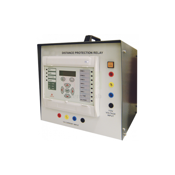
Distance Protection Relay
Distance Protection Relay (Product Code: SLE/EPS/12) is a relay module used to teach full-scheme phase and ground distance protection, with up to five zones, in power system protection laboratories. Based on the Micom industrial relay, it also provides overcurrent, earth fault, negative sequence, thermal overload and broken conductor functions, programmed from its keypad or a computer. It is supplied by Jain Scientific Equipments Pvt Ltd (ScienceLab), Ambala, India.
Key Details
| Parameter | Detail |
|---|---|
| Relay | Based on the Micom industrial relay |
| Distance protection | Full scheme phase and ground distance protection, up to five zones |
| Overcurrent functions | Directional/non-directional phase overcurrent; directional/non-directional negative sequence overcurrent |
| Earth fault | Directional/non-directional earth fault |
| Other protection | Thermal overload protection; broken conductor |
| Element blocking | Blocking of any one protection element |
| Records | Creates fault and disturbance records |
| Programming | Keypad and display on the relay module, or Micom S1 software on a suitable computer |
| Test setup | Fault circuits set up on the Protection and Relay Test Set; relay module then connected to them |
| Product code | SLE/EPS/12 |
| Supplied by | Jain Scientific Equipments Pvt Ltd (ScienceLab), Ambala, India |
What Is the Distance Protection Relay Used For?
A distance relay judges how far away a fault is by comparing voltage and current — in effect measuring the impedance to the fault — and responds according to the zone the fault falls in. This module lets students program up to five zones of full-scheme phase and ground distance protection and see which zone responds to each fault set up on the Protection and Relay Test Set.
The same relay also covers directional and non-directional overcurrent, earth fault and negative sequence overcurrent, thermal overload and broken conductor detection, so one module supports a whole sequence of protection practicals. Its fault and disturbance records let students review each test afterwards, and blocking any one protection element shows how individual functions interact. Settings go in through the keypad or Micom S1 software on a suitable computer.
What to Specify When Ordering
- Whether you already have the Protection and Relay Test Set on which the fault circuits are set up.
- Whether the relay will be programmed from a computer with Micom S1 software.
- Number of relay modules required.
Supplier
Jain Scientific Equipments Private Limited trades as ScienceLab from Ambala, Haryana, India. It supplies the Distance Protection Relay, built around a Micom industrial relay, to universities, engineering colleges and training institutes, together with other engineering lab equipment in India and international markets.
Questions about the relay model, the software or spares are best raised at enquiry stage. Company details are on the ScienceLab profile.
Related Power & Energy Systems Trainers
Other relays and trainers used in the same protection course:
- Differential Protection Relay — Micom-based module for three-phase differential protection.
- Directional/Non-Directional Overcurrent Relay — three overcurrent stages with IDMT curves.
- Overcurrent And Earth Fault Relay — overcurrent and earth fault protection studies.
- Circuit Breaker Trainer — fuses and circuit-breakers under controlled fault currents.
Browse the Power & Energy Systems Trainers category for more.
Frequently Asked Questions
How many protection zones does the Distance Protection Relay offer?
The Distance Protection Relay (SLE/EPS/12) provides full-scheme phase and ground distance protection with up to five zones. Students program the zone settings and then test them against fault circuits set up on the Protection and Relay Test Set.
Which other functions does the Distance Protection Relay include?
Besides distance protection, the Distance Protection Relay offers directional/non-directional phase overcurrent, earth fault and negative sequence overcurrent, thermal overload protection, broken conductor detection, blocking of any one protection element, and fault and disturbance records.
How is the Distance Protection Relay programmed?
The Distance Protection Relay is programmed using the keypad and display on the relay module, or with Micom S1 software and a suitable computer. After programming, the relay module is connected to the fault circuits so tests can be performed.
Which relay is the module based on?
The Distance Protection Relay module is based on the Micom industrial relay, so students practise on real industrial relay hardware with its own keypad, display and settings rather than on a simplified classroom model.
Who supplies the Distance Protection Relay?
The Distance Protection Relay is supplied by Jain Scientific Equipments Pvt Ltd (ScienceLab), Ambala, Haryana, India, to institutions and dealers in India and international markets. Quotations are available through the ScienceLab contact page.
What should a quotation request include?
For a Distance Protection Relay quotation, state the quantity, whether you already have the Protection and Relay Test Set used to create the fault circuits, and whether you plan to program the relay with Micom S1 software on a computer.
Request a Quote
Send a Distance Protection Relay (SLE/EPS/12) enquiry through the contact page, or add it to the enquiry cart with the other relays and trainers for your protection lab.
Last updated: 24 September 2026

Directional/Non-Directional Overcurrent Relay
Directional/Non-Directional Overcurrent Relay (Product Code: SLE/EPS/13) is a programmable protection relay module used to teach overcurrent and earth fault protection, including IDMT time characteristics, in power system protection laboratories. It offers three independent overcurrent stages — the first selectable from 12 IDMT curves — plus voltage, undercurrent, thermal and negative phase sequence functions. It is supplied by Jain Scientific Equipments Pvt Ltd (ScienceLab), Ambala, India, a lab instruments supplier in India for engineering institutes.
Specifications
| Parameter | Detail |
|---|---|
| Overcurrent stages | Three independent stages of directional/non-directional phase overcurrent |
| Stage characteristics | First stage: any of 12 IDMT curves; remaining two stages: direct time characteristic |
| Earth fault | Directional/non-directional earth fault |
| Voltage and current functions | Undercurrent, undervoltage and overvoltage |
| Other protection | Thermal overload protection; negative phase sequence overcurrent |
| Blocking | Selectable blocking |
| Records | Creates fault and disturbance records |
| Enclosure | Robust enclosure with carrying handle |
| Mounting and connection | Mounts on the desk area of the Protection and Relay Test Set; connects by multi-core cable and safety leads |
| Programming | Keypad and display on the module, or Micom S1 software on a suitable computer |
| Product code | SLE/EPS/13 |
| Supplied by | Jain Scientific Equipments Pvt Ltd (ScienceLab), Ambala, India |
What Is the Directional Overcurrent Relay Used For?
Overcurrent protection is usually the first relay topic in a power systems course, and this module covers it in depth. Students select one of the 12 IDMT curves for the first stage, set the two direct time stages above it, and observe how the relay operates faster as fault current rises — the basis of grading relays along a feeder. Switching stages between directional and non-directional operation shows why fault direction matters on networks fed from more than one end.
Supporting functions are covered too: earth fault, negative phase sequence overcurrent, thermal overload, undercurrent, undervoltage and overvoltage. Most tests use a single relay: a fault circuit is set up on the Protection and Relay Test Set, the module is programmed by keypad or with Micom S1 software on a suitable computer, then connected with the multi-core cable and safety leads. Fault and disturbance records show what happened during each test.
What to Specify When Ordering
- Whether you already have the Protection and Relay Test Set the module mounts on.
- Whether you will program it from a computer using Micom S1 software.
- Number of modules — most tests are performed with a single relay.
Supplier
ScienceLab, the trading name of Jain Scientific Equipments Private Limited in Ambala, Haryana, India, supplies the Directional/Non-Directional Overcurrent Relay to engineering colleges, polytechnics and training institutes, alongside the other protection relays in its power systems range, for customers in India and international markets.
Please raise any questions about the relay model or the Micom S1 software when you enquire. You can read about the company on the ScienceLab profile page.
Related Power & Energy Systems Trainers
Relays and trainers that build on overcurrent protection practicals:
- Overcurrent And Earth Fault Relay — further overcurrent and earth fault protection studies.
- Distance Protection Relay — phase and ground distance protection up to five zones.
- Differential Protection Relay — three-phase differential protection characteristics.
- Circuit Breaker Trainer — fuse breaking-time behaviour to compare with IDMT curves.
Explore the complete Power & Energy Systems Trainers range.
Frequently Asked Questions
How many overcurrent stages does the Directional/Non-Directional Overcurrent Relay have?
The Directional/Non-Directional Overcurrent Relay (SLE/EPS/13) has three independent stages of directional/non-directional phase overcurrent. The first stage may be set to any of 12 IDMT curves, and the remaining two stages have a direct time characteristic.
Which other protection functions are included?
In addition to phase overcurrent, the Directional/Non-Directional Overcurrent Relay provides directional/non-directional earth fault, negative phase sequence overcurrent, thermal overload protection, undercurrent, undervoltage, overvoltage, selectable blocking, and creation of fault and disturbance records.
How does the relay connect to the Protection and Relay Test Set?
The Directional/Non-Directional Overcurrent Relay mounts on the desk area of the Protection and Relay Test Set and connects to it using a multi-core cable and safety leads. Its robust enclosure has a carrying handle for moving it between test sets.
How is the Directional/Non-Directional Overcurrent Relay programmed?
Program the Directional/Non-Directional Overcurrent Relay with the keypad and display on the module, or with Micom S1 software and a suitable computer. Once the settings are entered, the module is connected to the fault circuits and tests can be performed.
Do the tests need more than one relay?
Most tests with the Directional/Non-Directional Overcurrent Relay are performed using a single relay. If you plan grading or coordination exercises between several relays, mention this when requesting a quotation so ScienceLab can advise on quantities.
Who supplies the Directional/Non-Directional Overcurrent Relay?
The Directional/Non-Directional Overcurrent Relay is supplied by Jain Scientific Equipments Pvt Ltd (ScienceLab), Ambala, Haryana, India, to colleges, institutes and dealers in India and international markets. Enquiries go through our contact page.
Request a Quote
For a Directional/Non-Directional Overcurrent Relay (SLE/EPS/13) quotation, use the contact page or add the module to the enquiry cart along with your other protection lab items.
Last updated: 24 September 2026
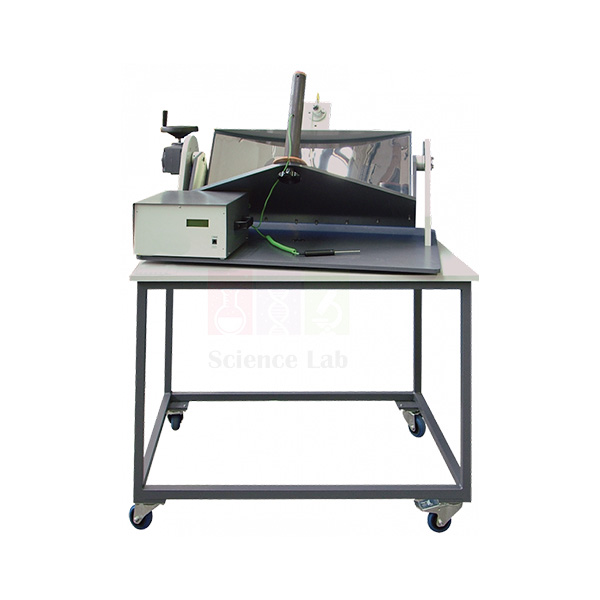
Focusing Solar Energy Collector
Focusing Solar Energy Collector (Product Code: SLE/ESA/05) is a parabolic-reflector solar concentrator on a mobile frame, used to demonstrate the principles, advantages and limits of focusing solar energy in engineering and renewable energy teaching labs. Students aim a polished stainless steel reflector at the sun and measure how hot copper collectors of four sizes become. It is made by Jain Scientific Equipments Pvt Ltd (ScienceLab), an OEM manufacturer, at its own factory in Ambala, India.
Key Details
| Parameter | Detail |
|---|---|
| Design | Focusing solar energy collector on a mobile frame, specially designed for educational use |
| Reflector | Highly polished stainless steel parabolic reflector |
| Reflector mounting | Trunnion bearings on a turntable; horizontal and vertical position adjustable |
| Energy collector | Copper cylinder with an embedded thermocouple that measures cylinder temperature |
| Collector sizes | Four different sizes supplied, for comparing concentration ratios |
| Radiation measurement | Solarimeter attached to the reflector carrier measures incident solar radiation |
| Ambient reference | Extra thermocouple measures ambient temperature |
| Collector cover | Removable transparent cover for shielded and unshielded collector studies |
| Product code | SLE/ESA/05 |
| Manufacturer | Jain Scientific Equipments Pvt Ltd (ScienceLab) — OEM |
| Country of origin | India (made in Ambala, Haryana) |
What Is the Focusing Solar Collector Used For?
Concentrating collectors reach higher temperatures than flat panels because a large reflector area focuses sunlight onto a small absorber. With this apparatus, students follow the sun by turning the reflector on its turntable and tilting it on its trunnions until the focus falls on the copper collector, then log collector temperature against ambient temperature and the solarimeter’s incident radiation reading.
Changing between the four collector sizes alters the concentration ratio, so groups can relate absorber size to the temperature reached; repeating a run with and without the transparent cover shows how a shielded collector behaves compared with an open one. The mobile frame makes it easy to take the unit outdoors on a clear day. Keep hands and eyes away from the focal point, where concentrated sunlight becomes very hot.
What to Specify When Ordering
- Number of units required for your student groups.
- How you plan to read and record the thermocouple and solarimeter signals, so the readout arrangement can be confirmed.
- Delivery location, within India or for export.
OEM Manufacturer
Jain Scientific Equipments Private Limited, whose brand is ScienceLab, is the OEM (original equipment manufacturer) of the Focusing Solar Energy Collector and makes it at its own licensed factory in Saha, Ambala, Haryana, India. Selling direct from the factory, the company supplies universities, polytechnics, energy-studies departments, dealers and importers without a middleman.
If you later need a replacement cover or collector, ask us — the manufacturer handles spares and repeat orders itself. The ScienceLab company profile has more background.
Related Power & Energy Systems Trainers
Pair the focusing collector with these items for a fuller solar energy practical:
- Flat Plate Solar Thermal Energy Collector — a non-concentrating collector for comparing efficiency and heat loss.
- Photovoltaic Cells — converting sunlight to electricity with battery storage.
- Mounted Solar Cell — an introductory solar cell for simple experiments.
- Digital Thermometer — independent temperature checks during outdoor runs.
The Power & Energy Systems Trainers category lists all solar, load and protection equipment.
Frequently Asked Questions
What does the Focusing Solar Energy Collector demonstrate?
The Focusing Solar Energy Collector (SLE/ESA/05) demonstrates the principles, advantages and limits of capturing solar energy by focusing. A polished stainless steel parabolic reflector concentrates sunlight onto a copper collector whose temperature is measured by an embedded thermocouple.
Why does it come with four collector sizes?
The Focusing Solar Energy Collector is supplied with four different sizes of copper energy collector so students can compare different concentration ratios and see how absorber size affects the temperature reached under the same reflector.
How is the reflector aimed at the sun?
The reflector of the Focusing Solar Energy Collector is supported on trunnion bearings on a turntable. Students adjust its horizontal and vertical position to keep solar energy focused on the collector as the sun moves across the sky.
What measurements does the Focusing Solar Energy Collector provide?
It measures collector temperature with a thermocouple embedded in the copper cylinder, ambient temperature with an extra thermocouple, and incident solar radiation with a solarimeter on the reflector carrier. Confirm the readout arrangement with ScienceLab through our contact page.
What is the transparent cover for?
The removable transparent cover on the Focusing Solar Energy Collector lets students run the same test with a shielded and an unshielded collector, and compare the properties of each type of collector.
Who manufactures the Focusing Solar Energy Collector?
The Focusing Solar Energy Collector is manufactured by Jain Scientific Equipments Pvt Ltd (ScienceLab), the OEM, at its own licensed factory in Saha, Ambala, Haryana, India, and supplied direct to institutions in India and international markets.
Request a Quote
Request a Focusing Solar Energy Collector (SLE/ESA/05) quotation through our contact page or add it to the enquiry cart. Quotations are prepared by the manufacturer in Ambala.
Last updated: 24 September 2026
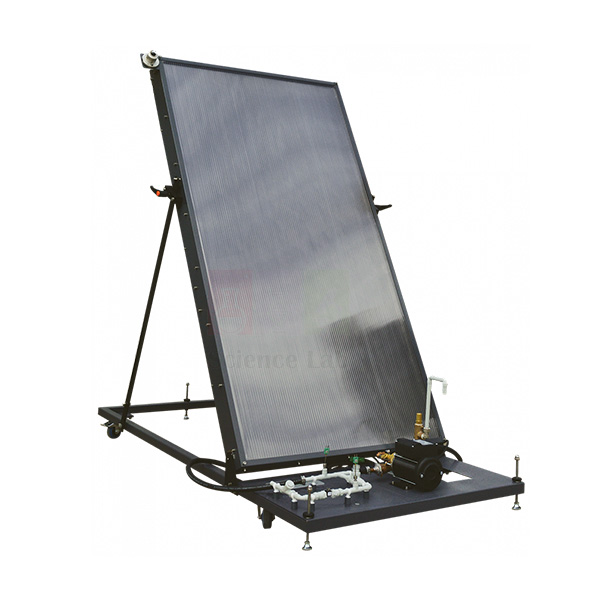
Flat Plate Solar Thermal Energy Collector
Flat Plate Solar Thermal Energy Collector (Product Code: SLE/ESA/06) is a water-heating solar collector on a hinged mobile frame, used to show how flat plate collectors work and to measure their efficiency and heat losses in engineering and energy laboratories. Cold mains water flows through a glazed, insulated absorber panel while a flow transducer and solarimeter record flow rate and incoming radiation. It is manufactured by Jain Scientific Equipments Pvt Ltd (ScienceLab), an OEM, at its own factory in Ambala, India.
Key Details
| Parameter | Detail |
|---|---|
| Principle | Flat plate solar energy collector heating cold mains water with sunlight |
| Collector construction | Purpose designed and built panel enclosed in a box with a clear cover |
| Absorber | Thin sheet metal absorber backed by riser tubes |
| Rear insulation | Insulating material to reduce heat loss to the rear |
| Water circuit | Cold mains water in; heated water returns to a pump that mixes it with incoming cold water |
| Outlet control | Pressure sensitive valve lets heated water leave at the same rate as cold water enters |
| Flow measurement | Flow transducer measures water flow rate |
| Radiation measurement | Solarimeter (or pyranometer) measures incident radiation |
| Frame | Sturdy mobile frame with a hinge to adjust the collector angle |
| Experiments | Efficiency and heat losses of a flat plate solar energy collector |
| Product code | SLE/ESA/06 |
| Manufacturer | Jain Scientific Equipments Pvt Ltd (ScienceLab) — OEM |
| Country of origin | India (made in Ambala, Haryana) |
What Is the Flat Plate Solar Collector Used For?
Flat plate collectors are the familiar rooftop solar water heaters, and this unit lets students study one under controlled conditions. Sunlight passing through the clear cover heats the sheet metal absorber, the riser tubes carry that heat into the water, and insulation behind the panel limits losses to the rear. The solarimeter shows how much energy arrives and the flow transducer how much water passes, forming the basis for working out efficiency and heat losses.
Adjusting the hinged frame changes the collector angle, so groups can compare performance at different tilts relative to the sun. The pump and pressure sensitive valve keep water moving steadily: heated water is mixed with incoming cold water, and water leaves the equipment at the same rate as it enters. Position the unit near a cold mains water supply and a drain before the practical begins.
What to Specify When Ordering
- The cold mains water supply and drain available where the collector will be used.
- The electrical supply available for the pump.
- How you plan to read and record the flow and radiation signals, so the readout arrangement can be confirmed.
- Number of units.
OEM Manufacturer
ScienceLab, the brand of Jain Scientific Equipments Private Limited, is the OEM (original equipment manufacturer) of the Flat Plate Solar Thermal Energy Collector and builds each unit at its own licensed factory in Saha, Ambala, Haryana, India. The company is registered as an MSME with manufacturing as its major activity (Udyam UDYAM-HR-01-0003714) and exports under DGFT Importer-Exporter Code AAECJ8618A.
As a science apparatus manufacturer in India selling factory-direct, ScienceLab quotes colleges, dealers and importers itself and answers spare-part questions directly — ask us. Read more on the ScienceLab profile.
Related Power & Energy Systems Trainers
Other equipment for solar and thermal energy practicals:
- Focusing Solar Energy Collector — a concentrating collector to compare with the flat plate design.
- Photovoltaic Cells — solar-to-electric conversion with charge control and storage.
- Digital Thermometer — for checking inlet and outlet water temperatures.
- Thermal Power Plant with Steam Engine Trainer — another heat-to-energy conversion trainer.
Browse more Power & Energy Systems Trainers, including solar and power systems equipment.
Frequently Asked Questions
How does the Flat Plate Solar Thermal Energy Collector work?
In the Flat Plate Solar Thermal Energy Collector (SLE/ESA/06), cold mains water enters the collector and is heated by sunlight falling on a thin sheet metal absorber backed by riser tubes. A box with a clear cover encloses the panel, and insulation reduces heat loss to the rear.
What can students measure with it?
The Flat Plate Solar Thermal Energy Collector lets students measure and find the efficiency and heat losses of a flat plate collector. A flow transducer measures the water flow rate and a solarimeter (or pyranometer) measures incident solar radiation.
Can the collector angle be adjusted?
Yes. The Flat Plate Solar Thermal Energy Collector sits on a sturdy mobile frame with a hinge, so users can adjust the collector angle relative to the sun and compare results at different tilts.
How is the water flow managed?
Heated water from the Flat Plate Solar Thermal Energy Collector returns to a pump that mixes it with incoming cold water, and a pressure sensitive valve lets heated water leave the equipment at the same rate as cold water enters it.
What services does the Flat Plate Solar Thermal Energy Collector need?
It is fed with cold mains water, so it needs a water supply and a drain nearby. Electrical supply details for the pump are not listed on this page; confirm them with ScienceLab through our contact page.
Who manufactures the Flat Plate Solar Thermal Energy Collector?
Jain Scientific Equipments Pvt Ltd (ScienceLab) manufactures the Flat Plate Solar Thermal Energy Collector as the OEM at its own licensed factory in Saha, Ambala, Haryana, India, supplying institutions and dealers in India and international markets.
Request a Quote
For a quotation on the Flat Plate Solar Thermal Energy Collector (SLE/ESA/06), contact us through the contact page or add it to the enquiry cart. The manufacturer replies directly with pricing and supply details.
Last updated: 24 September 2026
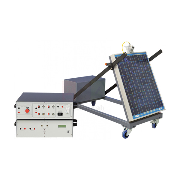
Photovoltaic Cells
Photovoltaic Cells (Product Code: SLE/ESA/07) is a solar photovoltaic trainer used to study how a solar panel, charge controller, battery storage and loads work together as one system in engineering and renewable energy labs. More advanced than a typical solar energy science kit, it lets students examine a full charge and discharge cycle within a single laboratory session. It is made by Jain Scientific Equipments Pvt Ltd (ScienceLab), an OEM manufacturer, at its own factory in Ambala, India, around a commercially available solar panel.
Key Details
| Parameter | Detail |
|---|---|
| Solar panel | Commercially available panel made from high efficiency cells |
| Panel frame | Wheeled, lightweight frame allowing adjustment of panel angle relative to the sun |
| Radiation measurement | Solarimeter on the frame measures incident radiation |
| Main battery | Deep cycling battery held in a storage box on the frame |
| Second battery | Lower rated battery; the panel recharges a choice of the two batteries |
| Control module | Contains the charge controller; digital displays show panel and battery storage performance |
| Charge controller | Recharges the battery at the correct rate of charge without damage; indicators for float mode and load cut mode |
| Separate loading unit | Variable resistive load, inverter for conversion to AC voltages, and four switchable lamps |
| Product code | SLE/ESA/07 |
| Manufacturer | Jain Scientific Equipments Pvt Ltd (ScienceLab) — OEM |
| Country of origin | India (made in Ambala, Haryana) |
What Is the Photovoltaic Cells Trainer Used For?
Students use this trainer to follow energy from sunlight to a working load. With the panel angled towards the sun and the solarimeter recording incident radiation, they watch the control module’s digital displays as the charge controller feeds the selected battery, and note when the indicator shows float mode.
The separate loading unit completes the picture. Its variable resistive load draws the battery down at a controlled rate to show battery performance, the inverter demonstrates practical conversion to AC, and the four switchable lamps represent a real lighting application. Continued discharge brings on load cut mode, showing how a charge controller disconnects loads to protect the battery; repeating the cycle on the lower rated second battery lets groups compare the two.
What to Specify When Ordering
- Number of trainers required.
- Confirmation of the scope of supply in your quotation: panel frame, control module, both batteries and the loading unit.
- Delivery destination — mention export early, because batteries can affect shipping arrangements.
OEM Manufacturer
Jain Scientific Equipments Private Limited, trading as ScienceLab, is the OEM (original equipment manufacturer) of the Photovoltaic Cells trainer. It is assembled at the company’s own licensed factory in Saha, Ambala, Haryana, India, around a commercially available solar panel, and supplied factory-direct to engineering colleges, polytechnics, renewable energy training centres, dealers and importers.
Because you deal directly with the manufacturer, questions about batteries, lamps or other replacement parts come straight to us — just ask. Background on the company is on the ScienceLab profile page.
Related Power & Energy Systems Trainers
Round out a solar energy laboratory with these items:
- Flat Plate Solar Thermal Energy Collector — solar water heating, efficiency and heat loss.
- Focusing Solar Energy Collector — concentrating solar thermal collection.
- Mounted Solar Cell — single-cell experiments for introductory classes.
- Digital Multimeter — independent panel and battery voltage checks.
All renewable and power systems equipment is listed under Power & Energy Systems Trainers.
Frequently Asked Questions
What does the Photovoltaic Cells trainer include?
The Photovoltaic Cells trainer (SLE/ESA/07) includes a commercially available solar panel on a wheeled frame, a solarimeter, a deep cycling battery in a storage box, a second lower rated battery, a control module with charge controller and digital displays, and a separate loading unit.
What is in the Photovoltaic Cells loading unit?
The separate loading unit of the Photovoltaic Cells trainer contains a variable resistive load to show battery performance, an inverter to show practical conversion to AC voltages, and four switchable lamps to show a practical application.
What do the float mode and load cut mode indicators show?
Indicators on the Photovoltaic Cells control module show when the charge controller is in float mode or load cut mode. The charge controller recharges the battery at the correct rate of charge without damage, and students can see each stage.
Can the solar panel angle be adjusted?
Yes. The solar panel of the Photovoltaic Cells trainer is mounted on a wheeled, lightweight frame that allows adjustment of the panel angle relative to the sun, and a solarimeter on the frame measures incident radiation.
Who manufactures the Photovoltaic Cells trainer?
Jain Scientific Equipments Pvt Ltd (ScienceLab), the OEM, builds the Photovoltaic Cells trainer at its own licensed factory in Saha, Ambala, Haryana, India. The solar panel itself is a commercially available panel made from high efficiency cells.
What does a quotation need?
For a Photovoltaic Cells quotation, give ScienceLab the quantity and the delivery destination in India or international markets through our contact page. Mention export early, because the batteries supplied with the trainer can affect shipping arrangements.
Request a Quote
Send your Photovoltaic Cells (SLE/ESA/07) enquiry via the contact page or add it to the enquiry cart. Quotations come directly from the manufacturer, ScienceLab, Ambala.
Last updated: 24 September 2026
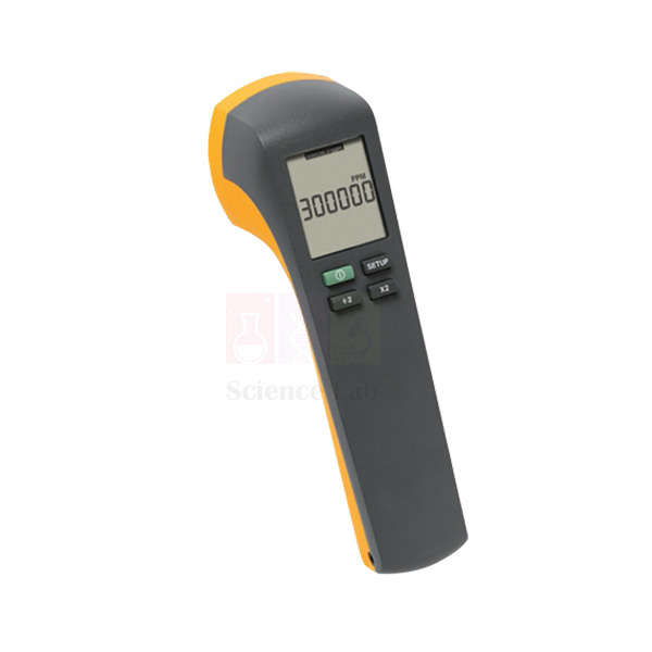
Stroboscope
Stroboscope (Product Code: SLE/EPS/14) is a portable digital LED stroboscope used for speed measurement and motion studies in engineering, physics and general laboratories. Its white LED flash runs from an internal oscillator over two frequency ranges or from an external trigger, and it doubles as a strobe tachometer that can “stop” a shaft down to 30 RPM. It is supplied by Jain Scientific Equipments Pvt Ltd (ScienceLab), Ambala, India, as part of its digital measuring instruments range.
Specifications
| Parameter | Detail |
|---|---|
| Type | Portable digital stroboscope for general laboratory use |
| Light source | High efficiency LED solid-state light source on the front; white light flash |
| Controls and display | Rear panel with the stroboscope controls and a liquid crystal display |
| Operating modes | Two: internal oscillator and external trigger |
| Internal oscillator | Continuous flash over two frequency ranges |
| External trigger | Another frequency generating device controls the flash rate |
| Tachometer use | Works as a strobe tachometer to measure speed instead of a laser tachometer |
| Lowest “stop” speed | Can “stop” a shaft down to 30 RPM (FPM) |
| Product code | SLE/EPS/14 |
| Supplied by | Jain Scientific Equipments Pvt Ltd (ScienceLab), Ambala, India |
What Is the Stroboscope Used For?
A stroboscope makes a moving part appear frozen: when the flash rate matches the rotation, the shaft is lit in the same position every time. Students use it to read the speed of motors, fans and machine shafts without touching them, and to watch vibrating or rotating parts in apparent slow motion during motion studies.
For speed measurement, run the internal oscillator in the suitable frequency range and adjust until the target appears stationary, then read the flash rate on the rear-panel display. Because a shaft can also look still at whole-number fractions of its true speed, start high and come down to the first stationary image to avoid a false reading. In external trigger mode, another frequency-generating device sets the flash rate, which helps synchronise the flash with other experiments.
Supplier
ScienceLab, the trading name of Jain Scientific Equipments Private Limited in Ambala, Haryana, India, supplies this Stroboscope to engineering colleges, physics departments, schools and training institutes as part of its test and measurement instruments in India and international markets.
For the exact frequency ranges, power arrangement and accessories of the unit you are quoted, ask us before ordering. Company details are on the ScienceLab profile.
Related Power & Energy Systems Trainers
Items to use with, or instead of, the Stroboscope:
- Xenon Stroboscope — an alternative stroboscope with a xenon flash source.
- Demonstration Motor AC/DC — a rotating shaft for practising strobe speed measurement.
- Electric Motor — a simple motor for motion and speed studies.
- Power System Simulator Generator — a motor-generator set whose running speed can be checked.
More equipment is available in Power & Energy Systems Trainers.
Frequently Asked Questions
What is the Stroboscope used for?
The Stroboscope (SLE/EPS/14) is a portable digital stroboscope for general laboratory use, such as speed measurement and motion studies. Its white LED flash makes rotating or vibrating parts appear stationary so they can be observed or their speed measured.
What operating modes does the Stroboscope have?
The Stroboscope has two modes of operation: internal oscillator and external trigger. The internal oscillator produces a continuous flash over two frequency ranges, while external trigger lets another frequency-generating device control the flash rate.
Can the Stroboscope be used as a tachometer?
Yes. The Stroboscope can be used as a strobe tachometer to measure speed instead of a laser tachometer, and it can “stop” a shaft down to 30 RPM (FPM). No contact with the rotating part is needed.
What light source and display does it use?
The Stroboscope emits a white light flash from a high efficiency LED solid-state light source on the front of the unit. The controls and a liquid crystal display are on the rear panel, so the operator reads settings while aiming the flash.
What are the two frequency ranges?
The exact limits of the Stroboscope’s two internal frequency ranges are not listed on this page. Ask ScienceLab through our contact page for the ranges of the unit you are quoted before placing an order.
Is a calibration certificate available?
Calibration-certificate availability for the Stroboscope should be discussed with ScienceLab before ordering, particularly if it will be used as a strobe tachometer for recorded speed measurements. Raise it through the contact page along with your quantity.
Who supplies the Stroboscope?
The Stroboscope is supplied by Jain Scientific Equipments Pvt Ltd (ScienceLab), Ambala, Haryana, India, to schools, colleges, training institutes and dealers in India and international markets, with quotations issued on request.
Request a Quote
Enquire about the Stroboscope (SLE/EPS/14) through the contact page or add it to the enquiry cart, stating the quantity you need.
Last updated: 24 September 2026