- Physics Lab Equipment
- Chemistry Lab Equipment
- Biology Lab Equipment
- Anatomical Lab Equipment
- Learning
- Educational Lab Equipment
- Magnets
- Agriculture
- Astronomy
- Earth Science
- Geography Lab Equipment
- Safety Lab Coat
- Laboratory
- Meteorological
- Electricity & Magnetism
- Heat
- School Lab Equipment
- Lab Glassware
- Science Lab Equipment
- Tvet Lab Equipment
- Robotics Kits Supplier and Manufacturer for Schools India
- Math Lab Equipment Manufacturers and Exporters in Ambala
- STEM Kits Manufacturers and Supplier India
- Engineering Lab Equipment
- Hospital Lab Equipment
- Water, Sanitation & Hygiene Supplies
- Cold Chain, Solar & Communication Equipment
- Nutrition
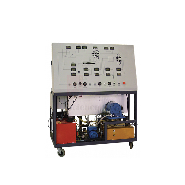
Two Shaft Gas Turbine
The Two Shaft Gas Turbine is a self-contained, fully instrumented trainer in which the gas generator and a separate power turbine turn on their own shafts. Students can see how a free power turbine takes useful work from the hot gas. Everything sits on a steel frame and is run from a labelled control panel with a mimic diagram.
Two shaft gas turbine specifications
| Parameter | Detail |
|---|---|
| Type | Self-contained, fully instrumented educational two-shaft gas turbine |
| Frame | Steel frame holding the gas generator, power turbine, combustion chamber, oil and fuel tanks, pumps, ancillaries and guards |
| Air path | Calibrated nozzle and air box, then compressor, then combustion chamber |
| Fuel system | Pump transfers fuel from the tank to spray through a special nozzle into the combustion chamber |
| Ignition | High-energy spark ignites the air and fuel mixture, which flows on to the gas generator turbine |
| Combustion chamber | Designed for good combustion, low pressure loss and good flame stability over varied operating conditions |
| Speed control | Fuel flow control valve on the instrumentation and control panel; design reduces the possibility of overspeed |
| Control panel | Clearly labelled, with schematic mimic diagram, instrument displays, controls and warning lights |
| Product code | SLE/EE/05 |
| Minimum order | 10 units |
| Dispatch | Usually within 7 to 10 working days |
| Manufacturer | ScienceLab (Jain Scientific Equipments Pvt Ltd), Ambala, India |
Gas turbine cycle tests on the two shaft trainer
Start-up and shutdown drill. With the guards in place and the oil and fuel tanks checked, students follow the start-up order shown on the mimic panel, calling out each step and each warning light before the instructor moves on. The shutdown sequence is practised the same way, so every student can run the trainer safely before any readings are taken.
Fuel flow against speed. Open the fuel flow control valve in small steps and let the turbine settle at each setting. Record the panel readings at every step, then plot speed and output against fuel flow and discuss why the gas generator and the power turbine respond at different rates.
Air flow and the cycle. Use the calibrated nozzle to find the air mass flow, then combine it with the other panel readings taken at the same fuel setting. Students draw the cycle on temperature-entropy axes and mark where the gas generator turbine drives the compressor and where the free power turbine delivers the useful output.
Placing the trainer in a course. The rotary air compressor test bench studies compression on its own beforehand, and the turbojet engine test bench shows the other way of using the hot gas, as a fast jet instead of shaft work. The temperature measurement and calibration apparatus covers the temperature-measurement methods used in engine testing.
Frequently Asked Questions About the Two Shaft Gas Turbine
What is gained by putting the power turbine on its own shaft?
The gas generator can run at the speed that suits its compressor, while the free power turbine turns at whatever speed the load needs. It also gives high torque at low output speed, which suits vehicles and pumps. Starting is easier too, because only the gas generator has to be spun up.
Why can a free power turbine overspeed if its load is suddenly lost?
The power turbine has no mechanical link to the compressor, so when its load drops away, hot gas from the gas generator keeps driving it faster. Fuel must be cut back quickly to slow the gas generator. On this trainer, speed is set with the fuel flow control valve, and the design reduces the possibility of overspeed.
What makes a gas turbine combustion chamber work well?
It must burn the fuel completely in a short space, lose as little pressure as possible and keep the flame stable when fuel flow changes quickly. It should also deliver gas at an even temperature, so that no part of the turbine blades runs too hot.
Why do measured results fall short of the theoretical Brayton cycle?
Real compressors and turbines are not isentropic, so the compressor needs more work and the turbines give less. Pressure is lost in the air box, combustion chamber and ducts, heat escapes through the casing and bearings absorb some power. The properties of the hot gas also change with temperature, which the simple cycle ignores.
How is the air flow found on the Two Shaft Gas Turbine?
Air enters through a calibrated nozzle and air box before it reaches the compressor. The nozzle allows the air flow to be determined, usually from the pressure drop across it together with the air temperature and the nozzle calibration. That mass flow is the starting point for the cycle calculations.
Why must the start-up order on the mimic panel be followed exactly?
Fuel and spark have to come in only when the gas generator is turning fast enough to supply air, or the combustion chamber can overheat or fail to light. Following the order on the mimic panel, with every guard in place, keeps each start the same and lets the warning lights do their job.
Trainers and apparatus for a thermal engineering lab
- Turbojet Engine Test Bench
- Rotary Air Compressor Test Bench
- Two Stage Compressor Test Set
- Temperature Measurement and Calibration Apparatus
- Thermal Power Plant with Steam Engine Trainer
To request a quotation, send the product name, code and quantity through our contact page or add the item to your enquiry cart.
Last updated: 20 November 2026