- Physics Lab Equipment
- Chemistry Lab Equipment
- Biology Lab Equipment
- Anatomical Lab Equipment
- Learning
- Educational Lab Equipment
- Magnets
- Agriculture
- Astronomy
- Earth Science
- Geography Lab Equipment
- Safety Lab Coat
- Laboratory
- Meteorological
- Electricity & Magnetism
- Heat
- School Lab Equipment
- Lab Glassware
- Science Lab Equipment
- Tvet Lab Equipment
- Robotics Kits Supplier and Manufacturer for Schools India
- Math Lab Equipment Manufacturers and Exporters in Ambala
- STEM Kits Manufacturers and Supplier India
- Engineering Lab Equipment
- Hospital Lab Equipment
- Water, Sanitation & Hygiene Supplies
- Cold Chain, Solar & Communication Equipment
- Nutrition
Fluid Mechanics lab equipment covers the hydrostatics, pipe-flow, open-channel and fluid-machinery experiments taught in mechanical, civil and chemical engineering degrees and polytechnic hydraulics diplomas. Jain Scientific Equipments Pvt Ltd (ScienceLab), Ambala, is the OEM behind this range and builds its rigs, from the Bernoulli's Theorem apparatus to Pelton and Francis turbines, at its own licensed factory in Ambala. With 48 listed products, a department can equip a complete hydraulics and hydraulic machines laboratory from one engineering lab equipment manufacturer.
What Does the Fluid Mechanics Range Include?
| Topic | What it covers | Example products |
|---|---|---|
| Hydrostatics and pressure measurement | Pressure on submerged surfaces, manometers, Bourdon gauges and gauge calibration | Pressure Measurement Bench, Calibration of a Pressure Gauge |
| Flow principles | Venturi flow, cavitation, forced vortices, falling-sphere viscosity and drag | Cavitation In Venturi, Vortex Apparatus, Viscosity And Particle Drag |
| Open-channel hydraulics | A laboratory flume plus accessories for gates, culverts, bridge piers and energy dissipation | Meter Flume, Sluice Gate with Tappings, Culvert, Bridge Piers, Energy Dissipation |
| Pumps, fans and compressors | Positive-displacement, axial and centrifugal machines, including two pumps run alone, in series or in parallel | Vane Pump, Gear Pump, Axial Flow Pump Module, Two Stage (Series And parallel), Centrifugal Fan Module, Reciprocating Compressor, Hydraulic Ram Pump |
| Drive and force measurement | Shared motor and load-cell drive unit for the fluid power machines; a force balance for models placed in a flume | Universal Dynamometer, Lift And Drag |
Featured Fluid Mechanics Apparatus
| Product | Product Code | Typical Use |
|---|---|---|
| Bernoulli's Theorem | SLE/EFM/10 | Showing the exchange of pressure and velocity head along a horizontal Venturi tube |
| Friction Loss In Pipe | SLE/EFM/09 | Measuring pipe friction losses in laminar and turbulent flow |
| Center of Pressure | SLE/EFM/28 | Locating the centre of pressure on a fully or partly submerged plane surface |
| Water Hammer Apparatus | SLE/EFM/18 | Capturing the pressure surge when a solenoid valve stops flow in a long copper pipe coil |
| Trapezoidal Flume | SLE/EFM/14 | Measuring low open-channel discharges through a clear 60° trapezoidal section |
| Pelton Wheel (Turbine) | SLE/EFM/05 | Impulse turbine study with a variable spear nozzle and a viewing window |
| Francis Turbine | SLE/EFM/04 | Reaction turbine study with adjustable guide vanes and a draft tube |
| Variable Speed Series And Parallel Pumps | SLE/EFM/29 | Comparing one variable-speed and one fixed-speed centrifugal pump alone, in series and in parallel |
OEM Manufacturing & Supply
ScienceLab (Jain Scientific Equipments Private Limited) manufactures the Fluid Mechanics range as the OEM at one licensed factory, located at 449, HSIIDC Industrial Area, Saha, Ambala, Haryana. Rigs are supplied factory-direct to universities, engineering colleges, polytechnics, dealers, tender buyers and importers in India and international markets, and every quotation is issued by the manufacturer itself. The works operate under Factory Licence AMB-ONLINE-CHD-J-414, and the company is a registered MSME with Udyam number UDYAM-HR-01-0003714.
Related Ranges
- Engineering Lab Equipment — the parent range linking every engineering teaching lab we make or supply.
- Aerodynamics Lab Equipment — wind tunnels and air-flow apparatus, the air-side counterpart to these mainly water-based rigs.
- Civil Engineering Lab Equipment — concrete, soil and construction-material testing for the same civil engineering departments.
- Theory of Machines — governors, cams, vibration and bearing apparatus for the mechanical dynamics lab.
Frequently Asked Questions
What does the Fluid Mechanics range include?
The Fluid Mechanics range includes 48 listed products covering hydrostatics, pressure measurement, Bernoulli and pipe-friction experiments, open-channel flume accessories, pumps and pump test rigs, a fan, a compressor, and Pelton and Francis turbines, so each topic of a hydraulics course has matching apparatus.
Can a complete hydraulics laboratory be set up from this range?
Yes. The Fluid Mechanics range spans fluid statics, pipe losses, open-channel flow and hydraulic machines, so a department can request one quotation for the whole lab. Some units, such as Friction Loss In Pipe, stand on a hydraulic bench, so mention your water supply.
Which courses use Fluid Mechanics equipment?
Fluid Mechanics equipment serves mechanical, civil and chemical engineering degree labs and polytechnic hydraulics and irrigation courses, where students verify flow equations, measure losses and test pumps and turbines instead of only reading about them.
Who manufactures the Fluid Mechanics range?
The Fluid Mechanics range is manufactured by Jain Scientific Equipments Private Limited (ScienceLab) at its licensed factory in Saha, Ambala, Haryana, and is supplied factory-direct to institutions, dealers, tender buyers and importers in India and abroad.
What details should a Fluid Mechanics quotation request include?
A Fluid Mechanics quotation request should give the product codes (SLE/EFM or SLE/MCE series), quantities, any flume length needed for the Meter Flume, the delivery destination, and whether the order is for a tender, a new laboratory or an export shipment.
Request a Quote or Catalogue
Share your experiment list on our contact page or collect rigs in the shopping cart, and our Ambala team will send a quotation or catalogue.
Last updated: 24 September 2026

Bernoulli's Theorem Demonstration module
Bernoulli's Theorem Demonstration module (Product Code: SLE/MCE/33) is a hydraulics-bench module used to verify Bernoulli's equation by measuring pressure along a convergent–divergent duct in fluid mechanics laboratories. Its 8-tube manometer reads 0 to 300 mm of water from pressure taps along the conduit, and a Pitot tube probe travels along the duct to measure the head in each section. It is made by Jain Scientific Equipments Pvt Ltd (ScienceLab), an OEM manufacturer, at its own factory in Ambala, India.
Specifications
| Parameter | Detail |
|---|---|
| Narrowing angle, downstream | 21° |
| Narrowing angle, upstream | 10° |
| Manometer range | 0 to 300 mm of water |
| Number of manometer tubes | 8 |
| Upstream diameter of the throat | 25 mm |
| Pressure taps | All connected to the manometer, which has a water collector (water may be pressurised) |
| Conduit | Removable ends, so the duct can be placed in convergent or divergent form relative to the flow direction |
| Probe | Pitot tube moving along the conduit, measuring the head in every section (dynamic pressure) |
| Flow control | Control valve at the end of the module adjusts flow rate and pressure in the module |
| Connections | Inlet pipe ending in a female coupling for direct connection to the bench supply; flexible hose on the outlet directed to the volumetric measuring tank |
| Mounting | Placed on the hydraulics bench top; adjustable legs for levelling |
| Construction | Anodized aluminium / MS powder-coated structure; panel of painted steel |
| Dimensions (approx.) | 800 x 450 x 700 mm |
| Weight (approx.) | 15 kg (33 pounds) |
| Product code | SLE/MCE/33 |
| Manufacturer | Jain Scientific Equipments Pvt Ltd (ScienceLab) — OEM |
| Country of origin | India (made in Ambala, Haryana) |
What Is the Bernoulli's Theorem Demonstration Module Used For?
Students set the module on the hydraulics bench, level it with the adjustable legs and connect the inlet coupling to the bench supply. With water flowing, the manometer tubes show static pressure falling where the duct narrows and recovering as it widens, while traversing the Pitot tube shows how the head changes from section to section. The control valve at the outlet end lets them repeat the readings at several flow rates.
Timing the collection of water in the bench's volumetric measuring tank gives the flow rate, from which students calculate velocities at each section and compare measured pressure heads with those predicted by Bernoulli's equation. Swapping the removable conduit ends switches between convergent and divergent arrangements, so the same practical also explores pressure recovery and energy losses. It is a classic experiment in mechanics lab equipment sets for civil, mechanical and chemical engineering courses.
OEM Manufacturer
Jain Scientific Equipments Private Limited, which trades as ScienceLab, is the original equipment manufacturer of the Bernoulli's Theorem Demonstration module. The module is fabricated and assembled at the company's own licensed factory in Saha, Ambala, Haryana, India, so universities, polytechnics, dealers and importers buy straight from the maker.
For supplier onboarding, institutions can quote the company's GSTIN 06AAECJ8618A1ZT together with its LEI 3358004HRD1JIVXKYX49. The ScienceLab profile has more about the company.
Related Fluid Mechanics Equipment
Other fluid mechanics apparatus that works alongside the Bernoulli's Theorem Demonstration module in a hydraulics laboratory:
- Orifice and Venturi meter demonstrator — applies Bernoulli's equation to flow measurement
- Flow Meter Demonstration Unit — compares different ways of measuring flow rate
- Friction Loss In Pipe — quantifies the head losses that also appear along the duct
- Bernoulli's Theorem — an alternative Bernoulli apparatus in the same range
- Bernoulli Tube Apparatus — a physics-lab demonstration of the same principle
Explore the full Fluid Mechanics category for turbines, pumps, flumes and pressure apparatus.
Frequently Asked Questions
Does the Bernoulli's Theorem Demonstration module need a hydraulics bench?
Yes. The Bernoulli's Theorem Demonstration module is placed on a hydraulics bench top, its inlet female coupling connects directly to the bench supply, and its outlet hose runs to the volumetric measuring tank. Ask us if you need to confirm fit with an existing bench.
How many manometer tubes does the Bernoulli's Theorem Demonstration module have?
The Bernoulli's Theorem Demonstration module has 8 manometer tubes with a range of 0 to 300 mm of water. All the pressure taps connect to this manometer, which includes a water collector.
Can the duct of the Bernoulli's Theorem Demonstration module be convergent or divergent?
Yes. The conduit ends of the Bernoulli's Theorem Demonstration module are removable, so the duct can be placed in either convergent or divergent form relative to the flow. The narrowing angles are 21° downstream and 10° upstream.
What is the Pitot tube on the Bernoulli's Theorem Demonstration module for?
The Pitot tube on the Bernoulli's Theorem Demonstration module is a probe that moves along the conduit and measures the head in each section, so students can compare it with the static readings from the manometer tubes.
What are the size and weight of the Bernoulli's Theorem Demonstration module?
The Bernoulli's Theorem Demonstration module measures approximately 800 x 450 x 700 mm and weighs about 15 kg (33 pounds). Its structure is anodized aluminium or MS powder coated, with a painted steel panel.
Who manufactures the Bernoulli's Theorem Demonstration module?
The Bernoulli's Theorem Demonstration module is manufactured by Jain Scientific Equipments Pvt Ltd (ScienceLab), the OEM, at its own licensed factory in Saha, Ambala, Haryana, India. Hydraulics laboratories can buy it factory-direct alongside other fluid mechanics apparatus.
Request a Quote
Request a quotation for the Bernoulli's Theorem Demonstration module through the contact page, or add it to the enquiry cart with any other hydraulics apparatus you need. Quotes are issued directly by the manufacturer, ScienceLab, for India and international markets.
Last updated: 24 September 2026
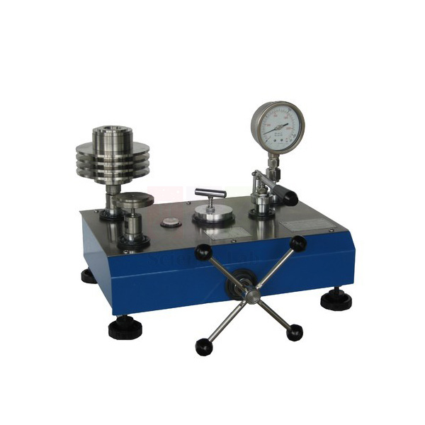
Dead Weight Pressure Gauge Calibrator
Dead Weight Pressure Gauge Calibrator (Product Code: SLE/MCE/34) is a portable deadweight tester used to calibrate pressure gauges, sensors and manometers by the direct p = F/A method in fluid mechanics and instrumentation laboratories. A capstan-operated hydraulic ram, balanced by weights acting on a piston of known area, generates pressures from 20 to 200 kN/m² with calibration accuracy better than 0.025% of reading. It is made by Jain Scientific Equipments Pvt Ltd (ScienceLab), an OEM manufacturer, at its own factory in Ambala, India.
Specifications
| Parameter | Detail |
|---|---|
| Pressure range | 20 kN/m² to 200 kN/m² |
| Calibration accuracy | Better than 0.025% of reading (deadweight method) |
| Minimum standard weight increment | 0.05 bar |
| Pistons | Dual pistons for calibration over a wide range of pressures; precision-machined piston and cylinder |
| Pressure generation | Capstan-operated hydraulic ram, balanced by deadweight acting on a piston of known area |
| Hydraulic fluid | Oil |
| Gauge fitted | Bourdon gauge with inlet and outlet valves |
| Gauges that can be calibrated | Pressure sensors, manometers or Bourdon gauges other than those supplied |
| Levelling | Spirit level, adjustable feet and levelling screws |
| Float indication | Flotation indicator mounted on the top plate |
| Dimensions | 450 x 400 x 300 mm |
| Weight | 30 kg |
| Included | Carrying case and weights |
| Format | Portable, self-contained bench-top unit |
| Product code | SLE/MCE/34 |
| Manufacturer | Jain Scientific Equipments Pvt Ltd (ScienceLab) — OEM |
| Country of origin | India (made in Ambala, Haryana) |
What Is the Dead Weight Pressure Gauge Calibrator Used For?
The calibrator shows students the most direct definition of pressure: force divided by area. Masses placed on the piston set the target pressure, the capstan-operated ram raises the system pressure until the piston floats, and the flotation indicator on the top plate removes the guesswork about when that balance is reached. The gauge under test sees the same pressure, so its error can be recorded at each step.
Besides the Bourdon gauge fitted, other pressure sensors, manometers or Bourdon gauges can be connected and calibrated, which makes the unit useful both for teaching and for checking gauges used elsewhere in a laboratory. Level the instrument with the spirit level and adjustable feet before each session, and keep the oil system clean to protect the precision-machined piston and cylinder. For institutions building up test and measurement instruments, it supports fluid mechanics, instrumentation and metrology practicals.
OEM Manufacturer
Jain Scientific Equipments Private Limited — the registered company behind the ScienceLab name — is the OEM of the Dead Weight Pressure Gauge Calibrator and produces it at its own licensed factory in Saha, Ambala, Haryana, India. Engineering colleges, instrumentation labs, dealers and importers therefore order direct from the manufacturer. Replacement weights or other spares can be requested from the same source; ask us about availability. Company details are on the ScienceLab profile.
Related Fluid Mechanics Equipment
Pressure-measurement apparatus that complements the Dead Weight Pressure Gauge Calibrator:
- Calibration of a Pressure Gauge — a further gauge-calibration setup in the fluid mechanics range
- Pressure Measurement Bench — compares different ways of measuring pressure
- Bourdon Gauge — a Bourdon-type pressure gauge for student measurements
- Hydrostatic Pressure Apparatus — studies the pressure of a liquid at rest
Find more hydraulics and pressure apparatus in the Fluid Mechanics category.
Frequently Asked Questions
What pressure range does the Dead Weight Pressure Gauge Calibrator cover?
The Dead Weight Pressure Gauge Calibrator covers 20 kN/m² to 200 kN/m², with dual pistons for calibration across the range and a minimum standard weight increment of 0.05 bar.
How accurate is the Dead Weight Pressure Gauge Calibrator?
The Dead Weight Pressure Gauge Calibrator calibrates pressure gauges by the deadweight method to an accuracy better than 0.025% of reading, using a precision-machined piston and cylinder of known area.
Can the Dead Weight Pressure Gauge Calibrator calibrate other gauges?
Yes. Besides the Bourdon gauge supplied, the Dead Weight Pressure Gauge Calibrator can calibrate other pressure sensors, manometers or Bourdon gauges; the pressure it develops is applied to the gauge being calibrated.
What is included with the Dead Weight Pressure Gauge Calibrator?
The Dead Weight Pressure Gauge Calibrator includes a carrying case and weights, along with its Bourdon gauge with inlet and outlet valves, spirit level, adjustable feet and flotation indicator. It uses oil as the hydraulic fluid.
Is a calibration certificate available for the Dead Weight Pressure Gauge Calibrator?
Calibration-certificate availability for the Dead Weight Pressure Gauge Calibrator should be discussed with us before you order. State the requirement in your enquiry through our contact page so it can be reviewed and answered in the quotation.
Who manufactures the Dead Weight Pressure Gauge Calibrator?
The Dead Weight Pressure Gauge Calibrator is manufactured by Jain Scientific Equipments Pvt Ltd (ScienceLab), the OEM, at its own licensed factory in Saha, Ambala, Haryana, India, and supplied factory-direct in India and international markets.
Request a Quote
For a Dead Weight Pressure Gauge Calibrator quotation, send your quantity and delivery details through the contact page or add the item to the enquiry cart. The quote comes straight from the manufacturer, Jain Scientific Equipments Pvt Ltd (ScienceLab).
Last updated: 24 September 2026
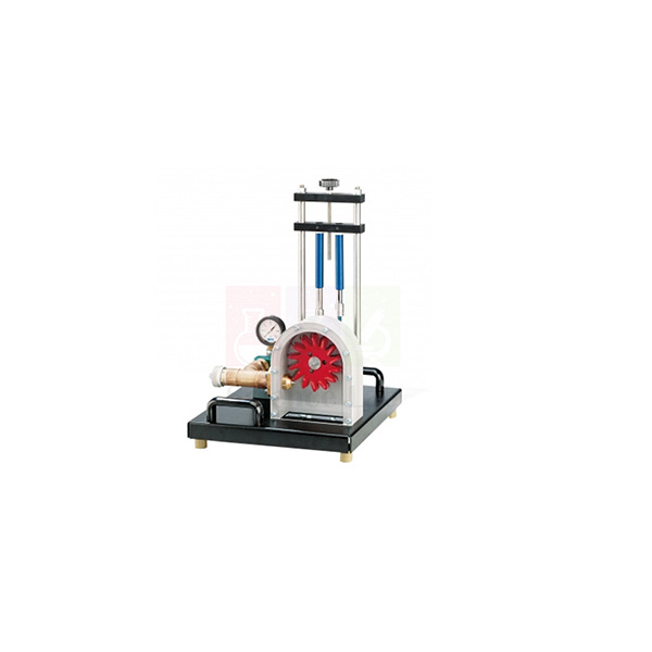
Demonstration Pelton Turbine
Demonstration Pelton Turbine (Product Code: SLE/MCE/35) is an impulse-turbine test unit used to show how a water jet drives a Pelton wheel and to measure turbine torque, inlet pressure and speed in fluid mechanics laboratories. It delivers about 5 W at 500 min-1 (rpm) with approximately 30 L/min at a 2 m head, using a 14-blade wheel of 132 mm external diameter and a 10 mm jet. It is made by Jain Scientific Equipments Pvt Ltd (ScienceLab), an OEM manufacturer, at its own factory in Ambala, India.
Specifications
| Parameter | Detail |
|---|---|
| Turbine type | Pelton turbine (impulse turbine) |
| Output | 5 W at 500 min-1, approx. 30 L/min, H = 2 m |
| Pelton wheel | 14 blades |
| Blade width | 33.5 mm |
| External diameter | 132 mm |
| Jet diameter | 10 mm |
| Jet deflection in the blades | Approximately 180° |
| Torque measurement | Force measurement on a band brake, read on spring balances |
| Force measuring range | 2 x 0–10 N |
| Inlet pressure measurement | Manometer at the turbine inlet, 0–1 bar |
| Speed measurement | Requires a non-contact speed sensor |
| Dimensions | 1000 x 800 x 1200 mm |
| Weight | 90 kg |
| Product code | SLE/MCE/35 |
| Manufacturer | Jain Scientific Equipments Pvt Ltd (ScienceLab) — OEM |
| Country of origin | India (made in Ambala, Haryana) |
What Is the Demonstration Pelton Turbine Used For?
In a Pelton turbine the pressure energy of the water is converted into kinetic energy entirely in the distributor: the jet is accelerated in a nozzle and directed tangentially onto the blades of the wheel. Each blade turns the jet back through roughly 180°, transferring the jet's impulse to the wheel — a clear, visible example of the impulse principle that students can contrast with reaction turbines.
During a test, students tighten the band brake in steps, read the spring balances to find the braking force and hence torque, note the inlet pressure on the manometer and measure rotational speed with a non-contact speed sensor. From these readings they plot torque and output power against speed to locate the turbine's most effective operating point. It is a valuable addition to mechanics lab equipment for mechanical and civil engineering hydraulics courses.
What to Specify When Ordering
- Number of units required for your laboratory
- Whether a non-contact speed sensor, needed for rotational-speed measurement, should be included in the quotation
- How water will be supplied to meet the stated operating point of approx. 30 L/min at H = 2 m
- Available space and handling for a 1000 x 800 x 1200 mm unit weighing 90 kg
OEM Manufacturer
The Demonstration Pelton Turbine is an OEM product of Jain Scientific Equipments Private Limited, the company that trades as ScienceLab. It is fabricated and assembled at the company's own licensed factory at Saha, Ambala, Haryana, India, and supplied directly to engineering colleges, polytechnics, dealers and importers without a trading middleman. Spare parts and repeat orders are handled by the manufacturer — just ask us. More on the company is on the ScienceLab profile.
Related Fluid Mechanics Equipment
Turbine and jet apparatus that extend the Demonstration Pelton Turbine practical:
- Pelton Wheel (Turbine) — another Pelton turbine unit in the range
- Pelton Turbine Test Rig — a test-rig version for Pelton performance studies
- Demonstration Francis Turbine — reaction-turbine counterpart for comparison with the impulse principle
- Impact of a Jet Apparatus — studies the force a water jet exerts on vanes
See all turbines, pumps and flow apparatus in the Fluid Mechanics category.
Frequently Asked Questions
What is the power output of the Demonstration Pelton Turbine?
The Demonstration Pelton Turbine delivers an output of 5 W at 500 min-1 with approximately 30 L/min of water at a head (H) of 2 m, which suits classroom performance measurements.
How is torque measured on the Demonstration Pelton Turbine?
Torque on the Demonstration Pelton Turbine is determined by force measurement on a band brake. The force is read on spring balances with a measuring range of 2 x 0–10 N and converted to torque by the students.
Is a speed sensor included with the Demonstration Pelton Turbine?
A non-contact speed sensor is required to measure the rotational speed of the Demonstration Pelton Turbine. Whether one is included depends on the quotation, so ask for it specifically when you enquire.
What are the Pelton wheel dimensions on the Demonstration Pelton Turbine?
The Demonstration Pelton Turbine's wheel has 14 blades of 33.5 mm width and an external diameter of 132 mm, and is driven by a 10 mm diameter water jet that the blades deflect by approximately 180°.
How large is the Demonstration Pelton Turbine?
The Demonstration Pelton Turbine measures 1000 x 800 x 1200 mm and weighs 90 kg, so plan floor space and handling accordingly. A manometer on the unit shows the inlet water pressure over 0–1 bar.
Who manufactures the Demonstration Pelton Turbine?
The Demonstration Pelton Turbine is manufactured by Jain Scientific Equipments Pvt Ltd (ScienceLab), the OEM, at its own licensed factory in Saha, Ambala, Haryana, India. Institutions can order it together with other fluid mechanics apparatus from the same manufacturer.
Request a Quote
To request a Demonstration Pelton Turbine quotation, use the contact page or add it to the enquiry cart, mentioning whether you need the speed sensor. Quotations come directly from the manufacturer, ScienceLab, for India and international markets.
Last updated: 24 September 2026
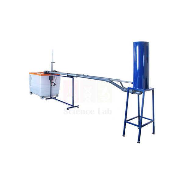
Pipe Surge and Water Hammer Apparatus
Pipe Surge and Water Hammer Apparatus (Product Code: SLE/MCE/37) is a fluid mechanics test rig used to demonstrate pipe surge and to measure water hammer pressure transients in engineering college and polytechnic laboratories. Students work with stainless steel test pipes 3 m long and 20.2 mm in bore, a fast-acting discharge valve, electronic pressure sensors and a clear acrylic surge shaft. It is made by Jain Scientific Equipments Pvt Ltd (ScienceLab), an OEM manufacturer of engineering lab equipment in India, at its own factory in Ambala.
Specifications
| Parameter | Detail |
|---|---|
| Test pipes | Stainless steel, 20.2 mm inside diameter |
| Test pipe length | 3 m |
| Water hammer pipe | Second test pipe with a fast-acting valve at the discharge |
| Pressure measurement | Tappings with electronic pressure sensors next to the fast-acting valve and half way along the test pipe |
| Surge shaft | Clear acrylic, 40 mm inside diameter, 800 mm high |
| Head tank | PVC, 45 litre capacity |
| Overall dimensions | 3500 x 800 x 1600 mm |
| Weight | 120 kg |
| Product code | SLE/MCE/37 |
| Manufacturer | Jain Scientific Equipments Pvt Ltd (ScienceLab) — OEM |
| Country of origin | India (made in Ambala, Haryana) |
What Is the Water Hammer Apparatus Used For?
When a valve at the end of a pipeline shuts quickly, the moving column of water is brought to rest and its momentum becomes a pressure wave that runs back up the pipe and reflects to and fro. On this rig students trigger that event with the fast-acting valve on the second test pipe, and the two electronic sensors capture the high-speed pressure transients as the wave travels backwards and forwards along the pipe.
Since one sensor sits beside the valve and the other half way along the pipe, the time delay between their signals gives the wave speed — the speed of sound in water, reduced by the elasticity of the metal pipe wall. The acrylic surge shaft makes the slower rise and fall of water level after a flow change visible, which links the experiment to surge tanks on hydropower and pumping mains. As lab equipment for technical institutes teaching hydraulics, it is best run with the head tank kept full and air cleared from the pipes so that repeated runs compare fairly.
OEM Manufacturer
Jain Scientific Equipments Private Limited, which trades as ScienceLab, is the OEM (original equipment manufacturer) of this Pipe Surge and Water Hammer Apparatus. The rig is built at the company's own licensed factory at 449, HSIIDC Industrial Area, Saha, Ambala, Haryana, not sourced from a trader. The company is incorporated under CIN U29309HR2020PTC087597, and the factory premises hold Factory Licence AMB-ONLINE-CHD-J-414.
Engineering colleges, universities, dealers and importers in India and international markets deal directly with the manufacturer, so questions about replacement valves, sensors or acrylic parts reach the people who build the rig — just ask us. More background is on the ScienceLab company profile.
Related Fluid Mechanics Equipment
These items from the same hydraulics range support pressure-transient, pipe-flow and pressure-measurement practicals:
- Water Hammer Apparatus — a separate water hammer set-up for comparing wave behaviour in a different pipe layout.
- Friction Loss In Pipe — covers steady-flow head loss, the companion topic to unsteady pipe flow.
- Fluid Friction Measurements — a larger pipe network trainer for losses in pipes, bends and fittings.
- Calibration of a Pressure Gauge — teaches how pressure instruments are checked before measurements are trusted.
See the complete Fluid Mechanics range for more hydraulics trainers and demonstration units.
Frequently Asked Questions
What does the Pipe Surge and Water Hammer Apparatus measure?
The Pipe Surge and Water Hammer Apparatus measures the high-speed pressure transients created when its fast-acting valve closes, using electronic pressure sensors beside the valve and half way along the 3 m test pipe. It also shows surge behaviour as a changing water level in a clear acrylic surge shaft.
How is the speed of sound in water found with this apparatus?
With the Pipe Surge and Water Hammer Apparatus, wave speed is worked out from the time delay between the two pressure sensors and their known spacing along the test pipe. The value obtained is lower than in open water, because the elastic metal pipe wall attenuates the wave.
What size are the test pipes and the surge shaft?
The test pipes of the Pipe Surge and Water Hammer Apparatus are stainless steel, 20.2 mm inside diameter and 3 m long. The surge shaft is clear acrylic with a 40 mm inside diameter and 800 mm height, and water is held in a 45 litre PVC head tank.
How much floor space does the apparatus need?
The Pipe Surge and Water Hammer Apparatus measures 3500 x 800 x 1600 mm overall and weighs 120 kg. Plan a long, level floor area with room along one side, so that students can operate the valve and watch the surge shaft and sensor readings.
How are the pressure sensor readings displayed?
The Pipe Surge and Water Hammer Apparatus picks up transients with electronic pressure sensors, but the display or data-recording arrangement offered with it should be confirmed at quotation. Please ask through the contact page which readout is supplied for your order.
Who manufactures the Pipe Surge and Water Hammer Apparatus?
The Pipe Surge and Water Hammer Apparatus is manufactured by Jain Scientific Equipments Pvt Ltd (ScienceLab), the OEM, at its own factory in Saha, Ambala, Haryana, India. It is supplied factory-direct to colleges, institutions, dealers and importers.
Is a calibration certificate available for the sensors?
Calibration certificate availability for the sensors on the Pipe Surge and Water Hammer Apparatus should be discussed with us before you order. State your requirement in the enquiry so that it can be answered in the quotation.
Request a Quote
To request a quotation for the Pipe Surge and Water Hammer Apparatus (SLE/MCE/37), send your quantity and delivery location through the contact page or add it to the enquiry cart. Quotations come directly from the manufacturer in Ambala for single laboratory sets and larger institutional orders.
Last updated: 24 September 2026
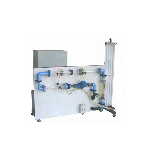
Orifice and Venturi meter demonstrator
Orifice and Venturi meter demonstrator (Product Code: SLE/MCE/38) is a flow measurement teaching unit used to compare a Venturi meter, a variable area meter and an orifice plate in hydraulics laboratories. The three meters sit in series on one circuit, read against an 8-tube manometer of 0 to 500 mm water column, and the unit stands on a hydraulics bench for its water supply. It is made by Jain Scientific Equipments Pvt Ltd (ScienceLab), an OEM manufacturer, at its own factory in Ambala, India.
Specifications
| Parameter | Detail |
|---|---|
| Flow meters | Venturi meter, variable area meter and orifice plate, installed in series |
| Variable area meter range | 2 to 30 l/min |
| Manometer | 8 tubes, 0 to 500 mm water column, pressurised with a hand pump |
| Venturi upstream pipe diameter | 32 mm |
| Venturi throat diameter | 20 mm |
| Venturi taper angles | 21° and 14° |
| Orifice plate | Upstream pipe diameter 35 mm, orifice diameter 19 mm (an orifice plate diameter of 25 mm is also listed — confirm when ordering) |
| Flow control | Flow control valve to vary the flow rate through the circuit |
| Head loss measurement | Pressure tappings across each flow meter |
| Mounting and water supply | Support framework standing on the working top of a hydraulics bench, which supplies water and is used for volumetric calibration |
| Product code | SLE/MCE/38 |
| Manufacturer | Jain Scientific Equipments Pvt Ltd (ScienceLab) — OEM |
| Country of origin | India (made in Ambala, Haryana) |
What Is the Orifice and Venturi Meter Demonstrator Used For?
Differential-pressure flow meters are everywhere in water supply and process plants, and this demonstrator lets students see how three common types behave when exactly the same flow passes through each. They set a flow with the control valve, read the manometer levels at the tappings, and then collect a timed volume in the bench tank to find the true flow rate for comparison.
From those readings a class can work out the coefficient of discharge of the Venturi and the orifice plate, check the variable area meter scale, and compare the permanent head loss each meter causes — the Venturi recovers most of its pressure drop, while the orifice plate does not. Repeating the test at several valve settings across the 2 to 30 l/min range builds calibration curves, a staple exercise for engineering educational equipment in India's polytechnics and colleges.
What to Specify When Ordering
- Whether your laboratory already has a hydraulics bench to supply water and measure volume, since the demonstrator stands on one.
- Confirmation of the orifice plate dimensions required for your syllabus.
- Number of units, based on how many student groups run the experiment at once.
OEM Manufacturer
This Orifice and Venturi meter demonstrator is manufactured by Jain Scientific Equipments Private Limited, the company behind the ScienceLab brand. As the OEM (original equipment manufacturer), ScienceLab builds and assembles the meter circuit, manometer board and framework at its own licensed factory at Saha, Ambala, Haryana, India.
Buying from the maker means one point of contact for quotations, repeat units for additional lab benches and replacement manometer tubes or fittings — ask us about the parts you need. Colleges, training institutes, dealers and importers are supplied factory-direct; the ScienceLab company profile has more about the company.
Related Fluid Mechanics Equipment
These products extend flow measurement practicals or support the calibration step:
- Flow Meter Demonstration Unit — a similar three-meter comparison unit with a 15 mm Venturi throat and a smaller meter range.
- Bernoulli's Theorem — studies the pressure and velocity changes along a converging-diverging section.
- Cavitation In Venturi — shows what happens when throat pressure falls too low.
- Bench Stopwatch — times the volumetric tank fill when calibrating each meter.
Browse the full Fluid Mechanics category for more hydraulics lab apparatus.
Frequently Asked Questions
Which flow meters does the Orifice and Venturi meter demonstrator compare?
The Orifice and Venturi meter demonstrator compares a Venturi meter, a variable area meter and an orifice plate installed in series. Because the same flow passes through all three, students can compare their readings and head losses directly at each valve setting.
Does the demonstrator need a hydraulics bench?
Yes. The Orifice and Venturi meter demonstrator stands on the working top of a hydraulics bench, which supplies the water and provides the volumetric tank used to calibrate each meter. If your laboratory has no bench, mention this in your enquiry.
What is the manometer range?
The Orifice and Venturi meter demonstrator uses an 8-tube manometer with a range of 0 to 500 mm water column. A hand pump pressurises the manometer so that the water levels can be brought within the readable part of the scale.
What are the Venturi meter dimensions?
The Venturi meter on the Orifice and Venturi meter demonstrator has a 32 mm upstream pipe diameter and a 20 mm throat diameter, with taper angles of 21° and 14° listed for its converging and diverging sections.
What flow range can be measured?
The variable area meter on the Orifice and Venturi meter demonstrator reads from 2 to 30 l/min. The flow control valve lets students set several flow rates within this range to build calibration curves for the Venturi meter and the orifice plate.
Who manufactures the Orifice and Venturi meter demonstrator?
The Orifice and Venturi meter demonstrator is manufactured by Jain Scientific Equipments Pvt Ltd (ScienceLab), the OEM, at its own factory in Ambala, Haryana, India, and quotations come straight from the manufacturer.
Is a calibration certificate supplied?
Calibration certificate availability for the Orifice and Venturi meter demonstrator should be discussed with us before ordering. Please state the requirement through the contact page so it is covered in your quotation.
Request a Quote
For a quotation on the Orifice and Venturi meter demonstrator (SLE/MCE/38), use the contact page or place it in the enquiry cart with your quantity and delivery location. Prices and terms are quoted direct by the manufacturer for buyers in India and international markets.
Last updated: 24 September 2026
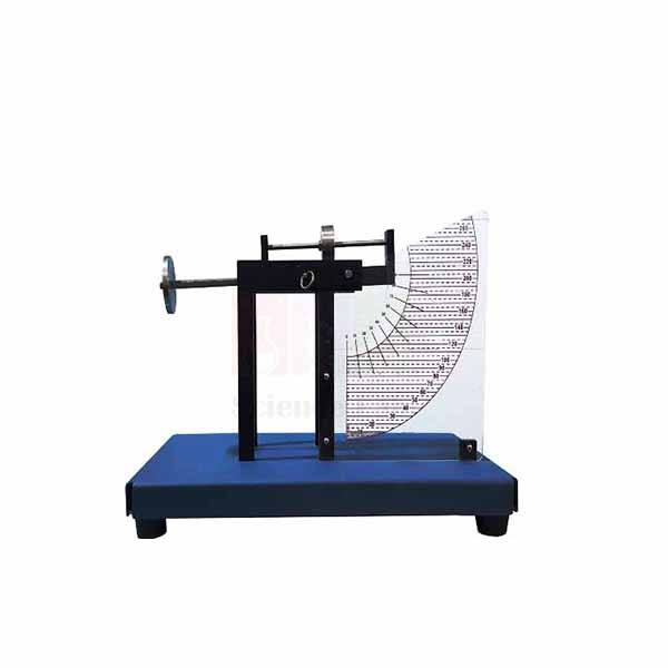
Hydrostatic Pressure Apparatus
Hydrostatic Pressure Apparatus (Product Code: SLE/MCE/39) is a fluid statics bench unit used to determine the resultant force and centre of pressure on a submerged plane surface in engineering and physics laboratories. Students hang masses from a swinging arm carrying a quadrant over a 5.5 litre acrylic tank, testing the face vertical or inclined and partly or fully under water. It is made by Jain Scientific Equipments Pvt Ltd (ScienceLab), an OEM manufacturer, at its own factory in Ambala, India.
Specifications
| Parameter | Detail |
|---|---|
| Tank | Clear acrylic, 5.5 litre capacity, with graduated scale showing the water level |
| Levelling | Adjustable screwed feet and a circular spirit level on the tank base |
| Balance arm | Swinging arm with a tray and an adjustable counterbalance, mounted on top of the tank |
| Area of the section | 0.007 m² |
| Total depth of submerged quadrant | 160 mm |
| Height of support point on the quadrant | 100 mm |
| Distance from suspended masses to support point | 285 mm |
| Dimensions | 600 x 400 x 400 mm |
| Weight | 30 kg |
| Product code | SLE/MCE/39 |
| Manufacturer | Jain Scientific Equipments Pvt Ltd (ScienceLab) — OEM |
| Country of origin | India (made in Ambala, Haryana) |
Experiments listed for the apparatus:
- Centre of pressure and resultant force with the surface at 90°, partially submerged.
- Centre of pressure and resultant force with the surface at 90°, totally submerged.
- Centre of pressure, resultant force and equivalent force with the surface at angles other than 90°, partially and totally submerged.
- Balance of moments about the support point.
What Is the Hydrostatic Pressure Apparatus Used For?
Dams, lock gates, tank walls and sluices all have to resist water pressure that grows with depth, so the resultant force acts below the centroid of the wetted face. This apparatus turns that idea into a measurement: with the tank levelled and the empty arm balanced by the counterbalance, students add water, restore balance by loading masses on the tray, and read the water level from the graduated scale.
Taking moments about the support point, with the masses acting 285 mm from it, gives the hydrostatic force and the depth of the centre of pressure, which are compared with theory for partial and full submersion. Tilting the face to angles other than 90° extends the exercise to inclined surfaces. It is compact bench-top engineering lab equipment in India's college syllabi and fits easily on a standard laboratory table.
OEM Manufacturer
Jain Scientific Equipments Private Limited (trading as ScienceLab) is the OEM, or original equipment manufacturer, of the Hydrostatic Pressure Apparatus. The acrylic tank, quadrant and balance arm assembly are made at the company's own licensed factory at Saha, Ambala, Haryana, so the product is supplied by the maker itself rather than by an intermediary.
Schools of engineering, polytechnics, dealers and importers can order single units or class sets straight from the factory, and later requests for spare quadrants or counterbalance parts go back to the same team — ask us. Company details are on the ScienceLab profile page.
Related Fluid Mechanics Equipment
Useful additions for a fluid statics practical session:
- Hangers with Slotted Weights — masses for balancing the hydrostatic moment on the arm.
- Center of Pressure — another centre-of-pressure set for comparing designs or equipping more groups.
- Fluid Properties and Hydrostatics Bench — a mobile bench covering density, viscosity, buoyancy and pressure measurement.
- Pressure Measurement Bench — extends the topic to manometers and pressure gauges.
More hydrostatics and hydraulics apparatus is listed in the Fluid Mechanics category.
Frequently Asked Questions
What experiments can be done with the Hydrostatic Pressure Apparatus?
The Hydrostatic Pressure Apparatus is used to find the resultant force and centre of pressure on a submerged surface at 90° and at other angles, partially and totally submerged, together with the equivalent force and a balance of moments about the support point.
What is the tank capacity?
The acrylic tank of the Hydrostatic Pressure Apparatus holds 5.5 litres of water. A graduated scale on the tank shows the water level reached, which students need for calculating the depth of the centre of pressure in each test.
What are the quadrant dimensions?
On the Hydrostatic Pressure Apparatus, the submerged quadrant has a total depth of 160 mm and a section area of 0.007 m². The support point sits 100 mm above the quadrant, and the suspended masses act 285 mm from the support point.
How is the apparatus levelled?
The Hydrostatic Pressure Apparatus is levelled with the adjustable screwed feet under its acrylic tank. Correct alignment is shown by a circular spirit level on the tank base, and the arm is then zeroed with the adjustable counterbalance before water is added.
Are the masses included with the apparatus?
The masses used on the tray of the Hydrostatic Pressure Apparatus should be confirmed at quotation, because the scope of supply is not listed here. Ask through the contact page, or add a set of slotted weights to your enquiry.
Who manufactures the Hydrostatic Pressure Apparatus?
The Hydrostatic Pressure Apparatus is manufactured by Jain Scientific Equipments Pvt Ltd (ScienceLab), which is the OEM and builds it at its own factory in Ambala, Haryana, India for colleges, institutions, dealers and importers.
Request a Quote
Ask for a quotation on the Hydrostatic Pressure Apparatus (SLE/MCE/39) through the contact page, or add it to the enquiry cart and state the number of units needed. Every quotation is prepared directly by the manufacturer, including for export orders.
Last updated: 24 September 2026
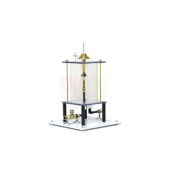
Impact of a Jet Apparatus
Impact of a Jet Apparatus (Product Code: SLE/MCE/40) is a hydraulics experiment unit used to measure the force a water jet exerts on flat and curved surfaces, so students can verify the momentum equation in fluid mechanics laboratories. An 8 mm jet inside a clear acrylic cylinder strikes interchangeable 40 mm targets — flat, 120° curved and 180° hemispherical — balanced by calibrated masses. It is made by Jain Scientific Equipments Pvt Ltd (ScienceLab), an OEM and engineering lab equipment manufacturer, at its own factory in Ambala, India.
Specifications
| Parameter | Detail |
|---|---|
| Construction | Cylindrical tank with transparent sides; discharge nozzle inside a clear acrylic cylinder |
| Jet diameter | 8 mm |
| Impact surfaces | 90° flat surface, 120° curved surface and 180° hemispherical surface |
| Impact surface diameter | 40 mm |
| Force measurement | Weight-loaded scale; the vertical jet force is balanced with calibrated weights |
| Masses supplied | Set of 5, 10, 50 and 100 g masses |
| Counterbalance | Compression spring offsets the dead weight of the moving parts |
| Water supply and drainage | Nozzle connected to a hydraulics bench; drain holes in the tank base |
| Dimensions | 800 x 800 x 800 mm |
| Weight | 90 kg |
| Product code | SLE/MCE/40 |
| Manufacturer | Jain Scientific Equipments Pvt Ltd (ScienceLab) — OEM |
| Country of origin | India (made in Ambala, Haryana) |
What Is the Impact of a Jet Apparatus Used For?
Turbine blades, spray nozzles and fire hoses all depend on the force produced when a moving stream of water changes direction. In this experiment the jet rises from the nozzle, hits the target and is deflected; the force it produces is found by adding calibrated weights until the lever returns to its level mark, while the flow rate is measured on the hydraulics bench.
Comparing the three targets shows why shape matters: the flat plate turns the jet through 90°, the 120° curved surface turns it further, and the hemispherical cup almost reverses it, giving the largest force for the same flow. Students plot measured force against the rate of momentum flow and compare the slope with theory. For a technical educational equipment manufacturer's customers — polytechnics and engineering colleges — it is also the natural lead-in to Pelton wheel tests.
OEM Manufacturer
ScienceLab is the brand name of Jain Scientific Equipments Private Limited, the original equipment manufacturer (OEM) of this Impact of a Jet Apparatus. It is fabricated and assembled at the company's own licensed factory at Saha, Ambala, Haryana, India, with the acrylic cylinder, lever system and target set built to go together.
Because you are dealing with the manufacturer, extra impact surfaces, replacement nozzles or additional mass sets can be requested from the same source that built the unit — ask us. Institutions, dealers and importers in India and international markets are served factory-direct; learn more on the ScienceLab company profile.
Related Fluid Mechanics Equipment
Products that follow on from jet impact studies or help with flow measurement:
- Pelton Turbine Test Rig — puts the same jet-deflection principle to work driving an impulse turbine.
- Pelton Wheel (Turbine) — another impulse turbine unit for performance tests.
- Orifice and Venturi meter demonstrator — a second accessory that runs on the same hydraulics bench.
- Bench Stopwatch — for timing the volume collected when measuring flow rate.
Explore the whole Fluid Mechanics category for more bench-top hydraulics experiments.
Frequently Asked Questions
What does the Impact of a Jet Apparatus measure?
The Impact of a Jet Apparatus measures the vertical force of an 8 mm water jet striking a target, by balancing it with calibrated weights on a weight-loaded scale. Students compare this force with the rate of momentum change calculated from the flow rate.
Which impact surfaces come with the apparatus?
The Impact of a Jet Apparatus has three impact surfaces, each 40 mm in diameter: a 90° flat surface, a 120° curved surface and a 180° hemispherical surface. Swapping them shows how deflection angle changes the jet force.
Are weights supplied with the Impact of a Jet Apparatus?
Yes. A set of 5, 10, 50 and 100 g masses is supplied with the Impact of a Jet Apparatus, and these calibrated weights are used on the weight-loaded scale to balance the force of the jet.
What water supply does the apparatus need?
The Impact of a Jet Apparatus has its nozzle connected to a hydraulics bench, which provides the water and is normally used to measure flow rate. Water leaves through holes in the tank base. If you do not have a bench, mention it when you enquire.
What is the compression spring for?
In the Impact of a Jet Apparatus, a compression spring counterbalances the dead weight of the moving parts. That way the calibrated weights added during a test balance only the force of the water jet, not the weight of the mechanism itself.
Who manufactures the Impact of a Jet Apparatus?
The Impact of a Jet Apparatus is manufactured by Jain Scientific Equipments Pvt Ltd (ScienceLab), the OEM, at its own factory in Ambala, Haryana, India, and it is supplied factory-direct to engineering institutions, dealers and importers.
Request a Quote
Send an enquiry for the Impact of a Jet Apparatus (SLE/MCE/40) through the contact page, or add it to the enquiry cart along with any other hydraulics units you need. The quotation comes directly from the manufacturer in Ambala.
Last updated: 24 September 2026
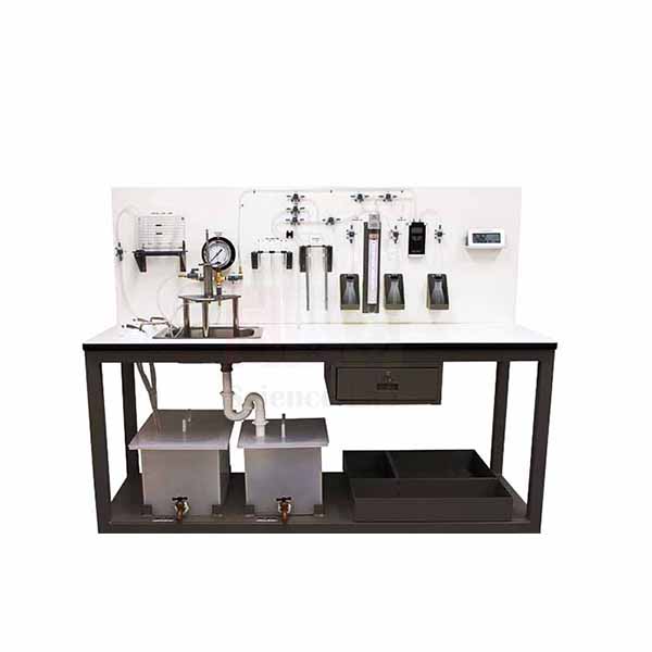
Fluid Properties and Hydrostatics Bench
Fluid Properties and Hydrostatics Bench (Product Code: SLE/MCE/41) is a mobile laboratory trolley used to teach density, viscosity, capillarity, buoyancy and pressure measurement in fluid mechanics courses. It carries its own sealed water circuit with a 0.22 kW submersible pump and a cabinet of modules, from falling-sphere viscometer tubes to an Archimedes set, so it works without a mains water connection. It is made by Jain Scientific Equipments Pvt Ltd (ScienceLab), an OEM manufacturer, at its own factory in Ambala, India.
Specifications
| Parameter | Detail |
|---|---|
| Construction | Laboratory trolley with demonstration panel, working area and cabinet; pipe section with pressure measuring devices and integrated measuring containers |
| Water circuit | Sealed circuit with pump and supply tank, independent of mains water |
| Submersible pump | 0.22 kW; flow rate 95 L/min; head 12.5 m |
| U-tube manometer | 0 to 500 mm water column |
| Mercury (Hg) U-tube manometer | 270–0–270 mbar |
| Aneroid barometer | 973 to 1047 mbar |
| Thermometer | -10 to 50 °C |
| Pycnometer | 50 ml |
| Hydrometer jars | Two, 450 x 50 mm |
| Falling sphere viscometer tubes | Two, 300 x 40 mm, with marks at 0, 25, 175, 200 and 220 |
| Stainless steel balls | 3.175 mm, 2.381 mm and 1.588 mm diameters |
| Capillary tubes module | Tubes of 5, 4, 3, 2.2, 1.7 and 1.2 mm |
| Other capillarity module | Parallel plates capillary module |
| Archimedes module | Displacement vessel, bucket and cylinder, used with a variable scale lever balance up to 310 g |
| Centre of pressure device | Included in the cabinet; also allows the pressure on a weir to be determined |
| Dimensions | 1000 x 800 x 1400 mm |
| Weight | 120 kg |
| Product code | SLE/MCE/41 |
| Manufacturer | Jain Scientific Equipments Pvt Ltd (ScienceLab) — OEM |
| Country of origin | India (made in Ambala, Haryana) |
What Is the Fluid Properties Bench Used For?
Before students move on to flowing water, they need a feel for the properties that govern it, and this bench gathers those first-semester practicals on one trolley. Density is found with the 50 ml pycnometer and the hydrometer jars, buoyancy with the Archimedes module and lever balance, and hydrostatic force with the centre of pressure device. The manometers and aneroid barometer compare gauge and atmospheric pressure readings.
For viscosity, steel balls of three sizes are dropped through the falling-sphere tubes and timed between the marks, giving data for Stokes' law. The capillary tubes module, from 5 mm down to 1.2 mm bore, turns into a classic capillary tube experiment for colleges in India, showing how rise height grows as the bore gets smaller, while the parallel plates show the same effect between flat surfaces. Being on a trolley, the bench can be wheeled between rooms and shared by several groups.
OEM Manufacturer
Jain Scientific Equipments Private Limited, known by its brand ScienceLab, is the OEM (original equipment manufacturer) of the Fluid Properties and Hydrostatics Bench. The trolley, pipe section and module cabinet are assembled at the company's own licensed factory at Saha, Ambala, Haryana. ScienceLab is a registered MSME enterprise whose major activity is manufacturing (Udyam UDYAM-HR-01-0003714), and export consignments are handled under Importer-Exporter Code AAECJ8618A (DGFT).
Colleges, universities, dealers and importers in India and international markets order direct from the factory, and replacement glassware or modules for the bench can be requested from the same team — ask us. Read more on the ScienceLab company profile.
Related Fluid Mechanics Equipment
Pair the bench with these units for a fuller fluid properties and statics course:
- Viscosity And Particle Drag — goes further into drag on particles settling through a fluid.
- Hydrostatic Pressure Apparatus — a dedicated bench-top centre of pressure rig for extra student groups.
- Pressure Measurement Bench — more practice with manometers and pressure gauges.
- Kinematic Viscometer Bath — a stirred, temperature-controlled bath for viscometer tube measurements.
The Fluid Mechanics category lists the complete hydraulics range.
Frequently Asked Questions
What experiments can be done on the Fluid Properties and Hydrostatics Bench?
The Fluid Properties and Hydrostatics Bench covers density with a pycnometer and hydrometer jars, falling-sphere viscosity, capillarity in tubes and between plates, Archimedes' principle, centre of pressure, pressure on a weir, and gauge and barometric pressure measurement.
Does the bench need a mains water connection?
No. The Fluid Properties and Hydrostatics Bench has a sealed water circuit with its own supply tank and a 0.22 kW submersible pump rated at 95 L/min and 12.5 m head, so experiments run independently of a mains water connection.
How is viscosity measured on the bench?
Viscosity is measured on the Fluid Properties and Hydrostatics Bench with two falling-sphere tubes, 300 x 40 mm, and stainless steel balls of 3.175, 2.381 and 1.588 mm. Students time each ball between the marks and apply Stokes' law.
Which pressure instruments are included?
The Fluid Properties and Hydrostatics Bench includes a U-tube manometer of 0 to 500 mm water column, a mercury U-tube manometer reading 270–0–270 mbar and an aneroid barometer with a 973 to 1047 mbar range, plus a -10 to 50 °C thermometer.
How large is the Fluid Properties and Hydrostatics Bench?
The Fluid Properties and Hydrostatics Bench measures 1000 x 800 x 1400 mm and weighs 120 kg. It is built on a laboratory trolley, so it can be moved between laboratories and shared by several student groups.
Who manufactures the Fluid Properties and Hydrostatics Bench?
The Fluid Properties and Hydrostatics Bench is manufactured by Jain Scientific Equipments Pvt Ltd (ScienceLab), the OEM, at its own factory in Ambala, Haryana, India. Quotations and spare-part requests are handled directly by the manufacturer.
Request a Quote
Request pricing for the Fluid Properties and Hydrostatics Bench (SLE/MCE/41) via the contact page, or add it to the enquiry cart with your delivery location. You receive the quotation directly from the manufacturer.
Last updated: 24 September 2026
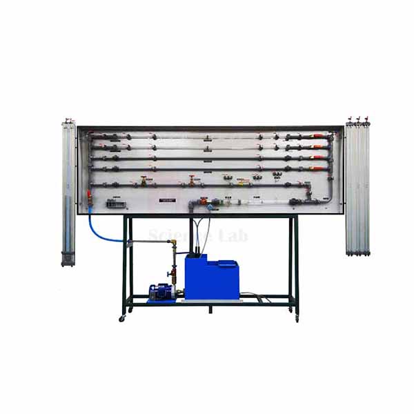
Fluid Friction Measurements
Fluid Friction Measurements (Product Code: SLE/MCE/42) is a pipe-flow trainer used to measure friction losses in straight pipes, fittings and flow meters in engineering and polytechnic hydraulics laboratories. It combines four smooth-bore pipes from 4.5 mm to 17.2 mm inside diameter, an artificially roughened pipe, a range of bends and elbows and 38 tapping points on one closed water circuit. It is made by Jain Scientific Equipments Pvt Ltd (ScienceLab), an OEM manufacturer, at its own factory in Ambala, India.
Specifications
| Parameter | Detail |
|---|---|
| Smooth-bore pipes | 4 pipes of different diameters, 4.5 mm to 17.2 mm inside diameter |
| Rough pipe | Artificially roughened pipe |
| Fittings | 90° bends (large and small radii), 90° elbow, 90° mitre, 45° elbow, 45° Y, 90° T |
| Other test sections | Inline strainer, Perspex Venturi, Perspex orifice meter, Perspex pipe section with Pitot tube and static tapping |
| Tapping points | 38, designed as annular chambers |
| Pressure | Bourdon tube pressure gauge, -1 to 1.5 bar |
| Differential pressure | 1 differential pressure sensor, 0 to ±350 mbar; 8 tube manometers, 0 to 1000 mm water column |
| Flow rate | Rotameter, 400 to 4000 L/h; volumetric measuring tank for timed measurements |
| Water circuit | Closed circuit with tank and submersible pump |
| Manometer panel | Movable, for space saving and easy access |
| Power supply | 230 V, 50 Hz, 1 phase |
| Dimensions | 800 x 800 x 1200 mm |
| Weight | 120 kg |
| Product code | SLE/MCE/42 |
| Manufacturer | Jain Scientific Equipments Pvt Ltd (ScienceLab) — OEM |
| Country of origin | India (made in Ambala, Haryana) |
What Is the Fluid Friction Apparatus Used For?
Every pipeline designer has to estimate how much head is lost to wall friction and fittings, and this trainer lets students measure those losses rather than just read them from charts. Water from the submersible pump is routed through one test section at a time; the pressure drop is read across the annular-chamber tappings and plotted against the flow rate, taken from the rotameter or from a timed fill of the volumetric tank.
Comparing the four smooth pipes shows how friction factor depends on Reynolds number, the roughened pipe brings in relative roughness, and the bends, elbows, mitre, Y and T give loss coefficients for fittings. The Perspex Venturi, orifice meter and Pitot tube add flow measurement to the same session. Use the stopwatch method at low flows, where it is more accurate than reading the rotameter. The trainer suits TVET lab equipment programmes in India as well as university hydraulics courses.
What to Specify When Ordering
- Electrical supply at the installation point: the trainer runs on 230 V, 50 Hz, single phase.
- Floor space for the 800 x 800 x 1200 mm unit and access around the movable manometer panel.
- Whether you need a stopwatch for the volumetric measurements.
- Number of trainers and the delivery location.
OEM Manufacturer
The Fluid Friction Measurements trainer is made by Jain Scientific Equipments Private Limited, which trades under the ScienceLab name and acts as the OEM (original equipment manufacturer). Pipework, fittings, manometer panel and frame are put together at the company's own licensed factory at Saha, Ambala, Haryana, rather than bought in from a reseller.
Quotations, repeat orders and requests for replacement pipe sections or manometer tubes all go to the manufacturer itself — ask us. Engineering colleges, training institutes, dealers and importers are supplied factory-direct; see the ScienceLab company profile for more.
Related Fluid Mechanics Equipment
Other items for pipe-flow and loss experiments:
- Friction Loss In Pipe — a simpler single-pipe unit for laminar and turbulent friction studies.
- Pipe Flow And Nozzle Kit — pipe loss and velocity-profile tests with air instead of water.
- Pipe Surge and Water Hammer Apparatus — moves on from steady to unsteady pipe flow.
- Bench Stopwatch — for timing the volumetric tank during flow measurement.
Find more hydraulics trainers in the Fluid Mechanics category.
Frequently Asked Questions
Which losses can be measured with the Fluid Friction Measurements trainer?
The Fluid Friction Measurements trainer measures friction losses in four smooth pipes and a roughened pipe, and local losses in 90° and 45° bends and elbows, a mitre, a Y, a T, an inline strainer, a Venturi and an orifice meter.
How is flow rate measured?
Flow rate on the Fluid Friction Measurements trainer is read from a rotameter covering 400 to 4000 L/h, or found by timing a fill of the volumetric measuring tank with a stopwatch, which gives accurate results even at low flow rates.
What pressure instruments does the trainer use?
The Fluid Friction Measurements trainer uses eight tube manometers of 0 to 1000 mm water column, a differential pressure sensor of 0 to ±350 mbar and a Bourdon tube pressure gauge reading -1 to 1.5 bar, connected to 38 tapping points.
Does it need a separate water supply?
No. The Fluid Friction Measurements trainer has a closed water circuit with its own tank and submersible pump, so it only needs filling with water and a 230 V, 50 Hz, single-phase electrical supply to operate.
Who manufactures the Fluid Friction Measurements trainer?
The Fluid Friction Measurements trainer is manufactured by Jain Scientific Equipments Pvt Ltd (ScienceLab), the OEM, at its own factory in Ambala, Haryana, India, and it is supplied direct to colleges, institutes, dealers and importers.
Can a calibration certificate be provided for the instruments?
Calibration certificate availability for the gauges and sensor on the Fluid Friction Measurements trainer should be discussed with us before ordering. Please raise it through the contact page so it is addressed in the quotation.
Request a Quote
Get a quotation for Fluid Friction Measurements (SLE/MCE/42) by writing to us on the contact page or adding it to the enquiry cart. Quotations are issued directly by the manufacturer for buyers in India and international markets.
Last updated: 24 September 2026
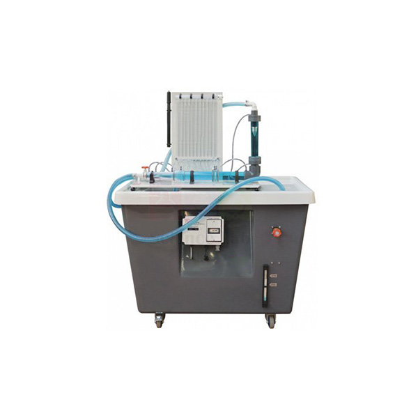
Flow Meter Demonstration Unit
Flow Meter Demonstration Unit (Product Code: SLE/MCE/43) is a hydraulics bench accessory used to compare and calibrate a Venturi meter, a variable area meter and an orifice plate in fluid mechanics laboratories. Its eight-tube manometer also traces the pressure curve along the Venturi, which has a 15 mm throat, while the variable area meter reads 2 to 20 l/min. It is made by Jain Scientific Equipments Pvt Ltd (ScienceLab), an OEM manufacturer of lab equipment for technical institutes, at its own factory in Ambala, India.
Specifications
| Parameter | Detail |
|---|---|
| Flow meters | Venturi meter, variable area meter and orifice plate, with a flow-control valve |
| Manometer board | 8 tubes, 0 to 400 mm range, pressurised with a hand pump |
| Venturi throat diameter | 15 mm |
| Upstream pipe diameter | 31.75 mm |
| Upstream taper | 21° inclusive |
| Downstream taper | 14° inclusive |
| Orifice plate diameter | 20 mm |
| Variable area meter | 2 to 20 l/min |
| Head loss measurement | Pressure tappings across each meter |
| Water supply and calibration | Placed on a hydraulics bench, which supplies the water and provides the volumetric measuring tank |
| Dimensions (as listed) | 800 x 800 x 1200 mm |
| Weight (as listed) | 120 kg |
| Product code | SLE/MCE/43 |
| Manufacturer | Jain Scientific Equipments Pvt Ltd (ScienceLab) — OEM |
| Country of origin | India (made in Ambala, Haryana) |
What Is the Flow Meter Demonstration Unit Used For?
The unit answers a practical question students will meet in industry: which meter should be fitted, and how far can its reading be trusted? With the circuit standing on the hydraulics bench, the class sets a flow on the control valve, reads the three meters, then collects water in the bench's volumetric tank against a stopwatch to get the true flow for calibrating each one.
Because the manometer tubes are spread along the Venturi, the same readings show the pressure falling into the 15 mm throat and recovering through the 14° diffuser — a direct check of Bernoulli's equation and of the continuity principle. The tappings across each device then reveal how much head each meter permanently costs the system. Pressurising the manometer with the hand pump keeps all eight levels on the scale at higher flows.
OEM Manufacturer
ScienceLab is the trading name of Jain Scientific Equipments Private Limited, and the company is the OEM (original equipment manufacturer) of this Flow Meter Demonstration Unit. The meter circuit, manometer board and support framework are produced at its own licensed factory at Saha, Ambala, Haryana, India, and the unit ships from there directly to the buyer.
Dealing with the maker helps when a laboratory later needs an additional unit, a new manometer tube or a replacement fitting — ask us and the request goes straight to production. Universities, polytechnics, dealers and importers in India and international markets are supplied factory-direct. More on the company: ScienceLab company profile.
Related Fluid Mechanics Equipment
Other bench accessories and aids for flow measurement practicals:
- Orifice and Venturi meter demonstrator — a comparable unit with a 20 mm Venturi throat and a wider 2 to 30 l/min meter.
- Bernoulli's Theorem — a dedicated unit for the pressure-velocity relationship.
- Impact of a Jet Apparatus — another experiment that runs from the same hydraulics bench.
- Stopwatch, Digital — times the volumetric tank for calibration.
The Fluid Mechanics category has the rest of the hydraulics range.
Frequently Asked Questions
Which flow meters does the Flow Meter Demonstration Unit include?
The Flow Meter Demonstration Unit includes a Venturi meter, a variable area meter and an orifice plate, with a flow-control valve and pressure tappings across each meter, so students can compare readings and head losses directly.
What manometer comes with the unit?
The Flow Meter Demonstration Unit is supplied with a manometer board of eight tubes and a 0 to 400 mm range. A hand pump pressurises the manometer so the levels stay readable, and several tubes trace the pressure curve along the Venturi.
What are the Venturi and orifice dimensions?
On the Flow Meter Demonstration Unit, the Venturi has a 31.75 mm upstream pipe diameter, a 15 mm throat, a 21° inclusive upstream taper and a 14° inclusive downstream taper. The orifice plate diameter is 20 mm.
Is a hydraulics bench required?
Yes. The Flow Meter Demonstration Unit is placed on a hydraulics bench, which supplies the water and provides the volumetric measuring tank used to calibrate each flow meter. Tell us in your enquiry if your laboratory does not have a bench.
What flow range does the variable area meter cover?
The variable area meter on the Flow Meter Demonstration Unit reads from 2 to 20 l/min. Within that range students set several flows with the control valve and plot calibration curves for the Venturi meter and the orifice plate.
Who manufactures the Flow Meter Demonstration Unit?
The Flow Meter Demonstration Unit is manufactured by Jain Scientific Equipments Pvt Ltd (ScienceLab), the OEM, at its own factory in Ambala, Haryana, India, and quotations come straight from the manufacturer.
Request a Quote
For prices and delivery terms on the Flow Meter Demonstration Unit (SLE/MCE/43), contact us through the contact page or add it to the enquiry cart. The manufacturer quotes directly for single units and institutional quantities.
Last updated: 24 September 2026
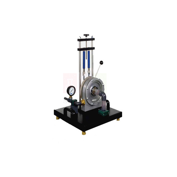
Demonstration Francis Turbine
Demonstration Francis Turbine (Product Code: SLE/MCE/44) is a small reaction water turbine used to study how guide vane setting, flow and speed affect turbine torque, power and efficiency in hydraulic machines laboratories. Rated at 350 W at 1500 rpm, it has a spiral housing, adjustable guide vanes, a band brake with spring balances and a non-contact speed sensor. It is made by Jain Scientific Equipments Pvt Ltd (ScienceLab), an OEM manufacturer, at its own factory in Ambala, India.
Specifications
| Parameter | Detail |
|---|---|
| Turbine type | Francis (reaction) turbine with spiral housing and adjustable guide vanes |
| Output | 350 W at 1500 rpm, 270 L/min, head approx. 15 m |
| Maximum speed | 3000 rpm |
| Rotor | 11 blades; 7 vanes |
| Medium diameter | 60 mm |
| Angle of attack | 0 to 20° |
| Torque measurement | Band brake read on spring balances, 0 to 9.81 Nm |
| Pressure measurement | Manometer at the turbine inlet, 0 to 4 bar absolute |
| Speed measurement | Non-contact speed sensor, 0 to 4000 rpm |
| Dimensions | 1000 x 800 x 1200 mm |
| Weight | 90 kg |
| Product code | SLE/MCE/44 |
| Manufacturer | Jain Scientific Equipments Pvt Ltd (ScienceLab) — OEM |
| Country of origin | India (made in Ambala, Haryana) |
What Is the Demonstration Francis Turbine Used For?
Francis turbines drive most medium-head hydropower stations, and this bench-scale version lets students follow the energy conversion step by step. Water enters through the spiral housing, is accelerated and turned by the adjustable guide vanes, and gives up both pressure and kinetic energy in the impeller — which is what makes it a reaction turbine rather than an impulse machine.
In a typical test the band brake is tightened in steps while students log spring balance forces, speed from the non-contact sensor and inlet pressure from the manometer. Torque times speed gives shaft power, and dividing by hydraulic power gives efficiency, so curves of power and efficiency against speed can be drawn for several guide vane angles between 0 and 20°. It is a compact choice among engineering lab equipment in India for hydraulic machines practicals where floor space is limited.
What to Specify When Ordering
- Your water supply arrangement: the rated output is quoted at 270 L/min and a head of approx. 15 m, so state whether a suitable pumped supply is already available.
- Number of turbines and whether other hydraulic machines are being ordered for the same laboratory.
- Delivery location in India or abroad, for packing and freight.
OEM Manufacturer
Jain Scientific Equipments Private Limited, trading as ScienceLab, is the OEM (original equipment manufacturer) of the Demonstration Francis Turbine. The turbine casing, guide vane mechanism, brake assembly and frame are made and assembled at the company's own licensed factory at Saha, Ambala, Haryana, India.
Colleges, dealers and importers therefore buy straight from the source, and later needs such as a replacement brake band or spring balance are handled by the same manufacturer — just ask us. Visit the ScienceLab company profile to learn more about the company.
Related Fluid Mechanics Equipment
Turbines and trainers that complement this unit in a hydraulic machines laboratory:
- Francis Turbine Trainer — a larger computer-linked Francis set with generator loading.
- Francis Turbine — a reaction turbine with a viewing window and draft tube.
- Demonstration Pelton Turbine — the impulse-turbine counterpart for side-by-side comparison.
- Pelton Turbine Test Rig — another band-brake turbine rig for performance tests.
See the Fluid Mechanics category for pumps, turbines and flow apparatus.
Frequently Asked Questions
What does the Demonstration Francis Turbine measure?
The Demonstration Francis Turbine measures torque through a band brake read on spring balances, rotational speed with a non-contact sensor and inlet water pressure with a manometer. From these, students calculate shaft power, hydraulic power and turbine efficiency.
What is the rated output of the Demonstration Francis Turbine?
The Demonstration Francis Turbine is rated at 350 W at 1500 rpm, with a flow of 270 L/min and a head of approximately 15 m. Its maximum speed is 3000 rpm.
How are the guide vanes adjusted?
The Demonstration Francis Turbine has adjustable guide vanes with an angle of attack from 0 to 20°. Changing the angle alters how the water is accelerated and directed onto the 11-blade rotor, so students can compare performance at several settings.
What are the measuring ranges?
The Demonstration Francis Turbine measures torque from 0 to 9.81 Nm, inlet pressure from 0 to 4 bar absolute and speed from 0 to 4000 rpm, which covers its full operating range up to the 3000 rpm maximum speed.
What water supply does the turbine need?
The Demonstration Francis Turbine delivers its rated 350 W at about 270 L/min and 15 m head. The supply arrangement to suit your laboratory should be confirmed at quotation, so please describe your set-up on the contact page.
Who manufactures the Demonstration Francis Turbine?
The Demonstration Francis Turbine is manufactured by Jain Scientific Equipments Pvt Ltd (ScienceLab), the OEM, at its own factory in Ambala, Haryana, India, and it is supplied factory-direct to institutions, dealers and importers.
Request a Quote
To receive a quotation for the Demonstration Francis Turbine (SLE/MCE/44), use the contact page or the enquiry cart, mentioning your water supply and delivery location. Quotations come directly from the manufacturer.
Last updated: 24 September 2026
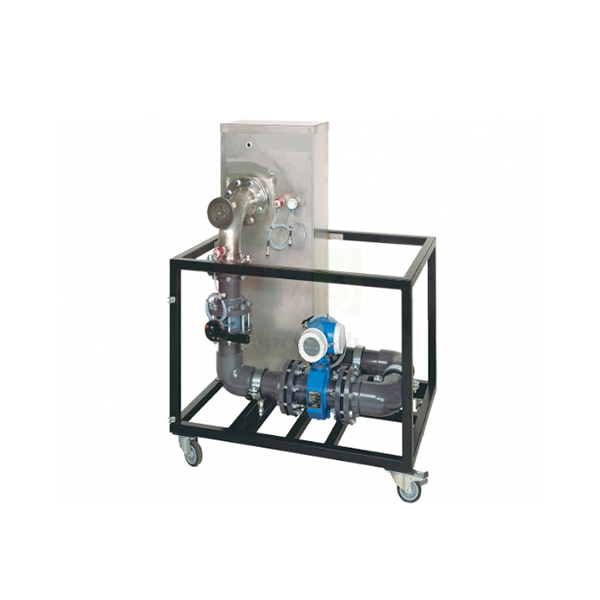
Axial Flow Pump Test Rig
Axial Flow Pump Test Rig (Product Code: SLE/MCE/45) is a pump trainer used to measure the operating behaviour of a propeller-type axial flow pump in hydraulic machines and fluid mechanics laboratories. Its 1000 W pump delivers up to 700 L/min at a maximum head of 1.75 m through a closed 160 L circuit with an electromagnetic flow meter. It is made by Jain Scientific Equipments Pvt Ltd (ScienceLab), an OEM manufacturer of vocational training lab equipment in India, at its own factory in Ambala.
Specifications
| Parameter | Detail |
|---|---|
| Pump type | Axial flow (propeller) pump, not self-priming |
| Pump output | 1000 W at 1000 rpm |
| Maximum flow rate | 700 L/min |
| Maximum head | 1.75 m |
| Tank | 160 L, closed water circuit independent of the mains water system |
| Flow measurement | Electromagnetic flow meter, 0 to 1200 L/min |
| Temperature measurement | Temperature sensor, 0 to 100 °C |
| Inlet pressure | ±1 bar |
| Outlet pressure | 0 to 0.6 bar |
| Power supply | 230 V, 50 Hz, 1 phase |
| Dimensions | 1110 x 800 x 1380 mm |
| Weight | Approx. 154 kg |
| Product code | SLE/MCE/45 |
| Manufacturer | Jain Scientific Equipments Pvt Ltd (ScienceLab) — OEM |
| Country of origin | India (made in Ambala, Haryana) |
What Is the Axial Flow Pump Test Rig Used For?
Where large volumes of water must be lifted only a short height — drainage systems, wastewater treatment plants and cooling water supply — engineers choose axial flow pumps. Unlike a centrifugal pump, the propeller builds pressure the way an aerofoil produces lift, with water passing straight through the impeller along the shaft axis. This rig lets students see how that design trades head for flow.
By logging inlet and outlet pressure together with electromagnetic flow readings at a series of operating points, students plot the head-flow characteristic and compare it with the steeper curves of centrifugal pumps. Because the pump is not self-priming, the propeller must stay covered by water: fill the 160 L tank before switching on and keep the level up during tests. The water temperature reading helps when calculating fluid properties for each run.
What to Specify When Ordering
- Electrical supply: the rig is specified for 230 V, 50 Hz, single phase.
- Installation space for the 1110 x 800 x 1380 mm frame, which weighs approx. 154 kg before the tank is filled.
- Number of rigs and delivery location, in India or overseas.
OEM Manufacturer
The Axial Flow Pump Test Rig comes from Jain Scientific Equipments Private Limited, which uses the brand name ScienceLab and is the OEM (original equipment manufacturer) of the rig. Frame, pipework, tank and instrument mounting are built at the company's own licensed factory at Saha, Ambala, Haryana, India. For institutional and tender buyers who need vendor registration details, the company's GSTIN is 06AAECJ8618A1ZT and its LEI is 3358004HRD1JIVXKYX49.
Buying factory-direct means the same manufacturer quotes, ships and answers later questions about spare sensors or pump parts — ask us whenever you need them. Engineering colleges, dealers and importers can read more on the ScienceLab company profile.
Related Fluid Mechanics Equipment
Pump trainers that help students compare different pump types:
- Axial Flow Pump Module — a modular axial pump unit that works with a common motive-power source.
- Variable Speed Series And Parallel Pumps — centrifugal pumps for contrasting head-flow curves.
- Computerized Gear Pump Test Rig — a positive displacement pump that delivers high head at low flow.
- Submersible Pump Test Rig — another variable-speed pump test set-up.
Browse the Fluid Mechanics category for the complete pump and turbine range.
Frequently Asked Questions
What is the maximum flow and head of the Axial Flow Pump Test Rig?
The Axial Flow Pump Test Rig delivers a maximum flow rate of 700 L/min and a maximum head of 1.75 m. Its pump output is 1000 W at 1000 rpm, typical of the high-flow, low-head duty axial pumps are chosen for.
Is the pump self-priming?
No. The pump in the Axial Flow Pump Test Rig is not self-priming, so the propeller must always be covered by water. Fill the 160 L tank of the closed circuit before starting and keep it filled while testing.
What does the rig measure?
The Axial Flow Pump Test Rig measures flow rate with an electromagnetic flow meter from 0 to 1200 L/min, water temperature from 0 to 100 °C, inlet pressure within ±1 bar and outlet pressure from 0 to 0.6 bar.
Does the rig need a mains water connection?
No. The Axial Flow Pump Test Rig runs on a closed water circuit with a 160 L tank, so it works independently of the building water system. It needs a 230 V, 50 Hz, single-phase electrical supply.
Where are axial flow pumps used in practice?
Axial flow pumps like the one on the Axial Flow Pump Test Rig are used where high flow rates and a small head are needed, typically in drainage systems, wastewater treatment plants and cooling water supply systems.
Who manufactures the Axial Flow Pump Test Rig?
The Axial Flow Pump Test Rig is manufactured by Jain Scientific Equipments Pvt Ltd (ScienceLab), the OEM, at its own factory in Ambala, Haryana, India. Quotations for institutions, dealers and importers come directly from the manufacturer.
Request a Quote
Request a quotation for the Axial Flow Pump Test Rig (SLE/MCE/45) on the contact page or add it to the enquiry cart. The manufacturer quotes directly, for laboratories in India and international markets.
Last updated: 24 September 2026
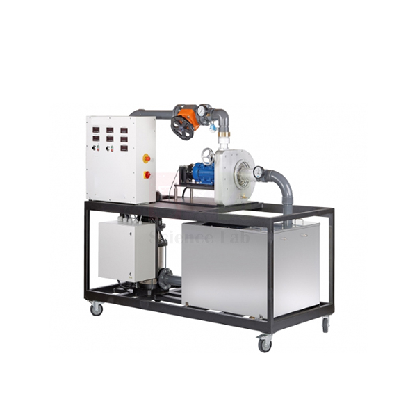
Francis Turbine Trainer
Francis Turbine Trainer (Product Code: SLE/MCE/46) is a floor-standing laboratory turbine test stand used to measure the performance of a Francis reaction turbine under generator load in university and technical institute hydropower labs. A multistage centrifugal pump with frequency-converter speed control feeds a 165 mm rotor with adjustable guide vanes, and all readings are shown digitally for further processing on a PC. It is made by Jain Scientific Equipments Pvt Ltd (ScienceLab), an OEM manufacturer, at its own factory in Ambala, India.
Specifications
| Parameter | Detail |
|---|---|
| Hydraulic power | 2.1 kW at 1500 rpm |
| Mechanical power | Approx. 1.4 kW at 1500 rpm |
| Rotor | 165 mm diameter, 8 blades, 8 guide vanes |
| Angle of attack | Adjustable, 0 to 23° |
| Operating area | Transparent, showing water flow, rotor and guide vanes |
| Supply pump | Multistage centrifugal pump, variable speed via frequency converter; head 42 m; max. flow rate 900 L/min |
| Inlet pressure control | Flow control valve |
| Tank | 550 L |
| Generator (load) | Asynchronous machine, 2.2 kW at 1440 rpm, 0 to 2200 W; pendulum bearing with force sensor for torque |
| Speed sensing | Inductive non-contact sensor on the generator shaft, 0 to 3000 rpm |
| Torque range | 0 to 20 Nm |
| Flow rate range | 0 to 1000 L/min |
| Temperature range | 0 to 100 °C |
| Turbine pressure sensors | Inlet and outlet; ranges listed as ±1 bar and 0 to 6 bar |
| Data | Digital display of measured values; can be processed further on a PC |
| Power consumption | 5.5 kW |
| Power supply | 400 V, 50 Hz, 3 phase (400 V, 60 Hz, 3 phase and 230 V, 60 Hz, 3 phase also listed) |
| Dimensions | 2350 x 1050 x 2050 mm |
| Weight | Approx. 580 kg |
| Product code | SLE/MCE/46 |
| Manufacturer | Jain Scientific Equipments Pvt Ltd (ScienceLab) — OEM |
| Country of origin | India (made in Ambala, Haryana) |
What Is the Francis Turbine Trainer Used For?
This trainer brings the working conditions of a small hydro set into the laboratory. The pump, running at a speed chosen on the frequency converter, supplies water at the required inlet pressure; the turbine drives an asynchronous machine working as a generator, whose pendulum-mounted housing and force sensor give torque directly. Speed, pressures, temperature and flow are all recorded by sensors.
Students change the guide vane setting between 0 and 23° to alter the angle of attack, flow cross-section and turbine output, then map torque, power and efficiency across the speed range to produce characteristic and hill-chart style curves. The transparent operating area makes the flow through the guide vanes and rotor visible while this happens. As lab equipment for technical institutes and universities with a hydropower or renewable energy syllabus, it supports project work as well as routine practicals.
What to Specify When Ordering
- Mains supply: 400 V, 50 Hz, 3 phase is the base specification; 400 V, 60 Hz, 3 phase and 230 V, 60 Hz, 3 phase are also listed.
- Space and floor loading for a 2350 x 1050 x 2050 mm unit of approx. 580 kg, plus water for the 550 L tank.
- Whether a PC and software are required for processing the measured values.
- Delivery location and site access for a unit of this size.
OEM Manufacturer
ScienceLab, the trading name of Jain Scientific Equipments Private Limited, is the OEM (original equipment manufacturer) of the Francis Turbine Trainer. The frame, turbine section, pipework and tank are fabricated and assembled at the company's own licensed factory at Saha, Ambala, Haryana, India, and the complete trainer is dispatched from there.
With a unit of this scale, a direct line to the maker matters: installation questions, spare sensors and repeat orders are handled by the manufacturer rather than a middleman — ask us. Universities, engineering institutes, dealers and importers in India and international markets are supplied factory-direct; see the ScienceLab company profile.
Related Fluid Mechanics Equipment
Other turbine and pump equipment for a hydraulic machines laboratory:
- Demonstration Francis Turbine — a compact 350 W Francis unit with band brake loading.
- Francis Turbine — a reaction turbine with viewing window and draft tube for guide vane studies.
- Pelton Turbine Test Rig — an impulse turbine for comparing turbine types.
- Variable Speed Series And Parallel Pumps — centrifugal pump behaviour, the supply side of the turbine circuit.
The Fluid Mechanics category lists the full range of turbines and pumps.
Frequently Asked Questions
How is the Francis Turbine Trainer loaded?
The Francis Turbine Trainer is loaded by an asynchronous machine used as a generator, rated 2.2 kW at 1440 rpm. Its pendulum bearing and force sensor measure torque from 0 to 20 Nm, and speed is read by an inductive non-contact sensor.
What power does the turbine develop?
The Francis Turbine Trainer is specified at 2.1 kW hydraulic power and approximately 1.4 kW mechanical power, both at 1500 rpm. Its 165 mm rotor has 8 blades, with 8 guide vanes adjustable from 0 to 23°.
Can the measurements be recorded on a PC?
Yes. The Francis Turbine Trainer displays its measured values digitally, and they can be processed further on a PC. Please confirm at quotation whether you need the computer and software included with the trainer.
What electrical supply does the trainer need?
The Francis Turbine Trainer is specified for 400 V, 50 Hz, 3 phase, with 400 V, 60 Hz, 3 phase and 230 V, 60 Hz, 3 phase also listed. Its power consumption is 5.5 kW, so a suitable three-phase connection is required.
How much space does the Francis Turbine Trainer need?
The Francis Turbine Trainer measures 2350 x 1050 x 2050 mm and weighs about 580 kg before its 550 L tank is filled, so plan a ground-floor laboratory position with adequate floor strength and access.
Who manufactures the Francis Turbine Trainer?
The Francis Turbine Trainer is manufactured by Jain Scientific Equipments Pvt Ltd (ScienceLab), the OEM, at its own factory in Ambala, Haryana, India, and quotations come directly from the manufacturer.
Request a Quote
Ask for a quotation on the Francis Turbine Trainer (SLE/MCE/46) through the contact page or add it to the enquiry cart, stating your power supply and delivery location. The manufacturer prepares every quotation directly.
Last updated: 24 September 2026
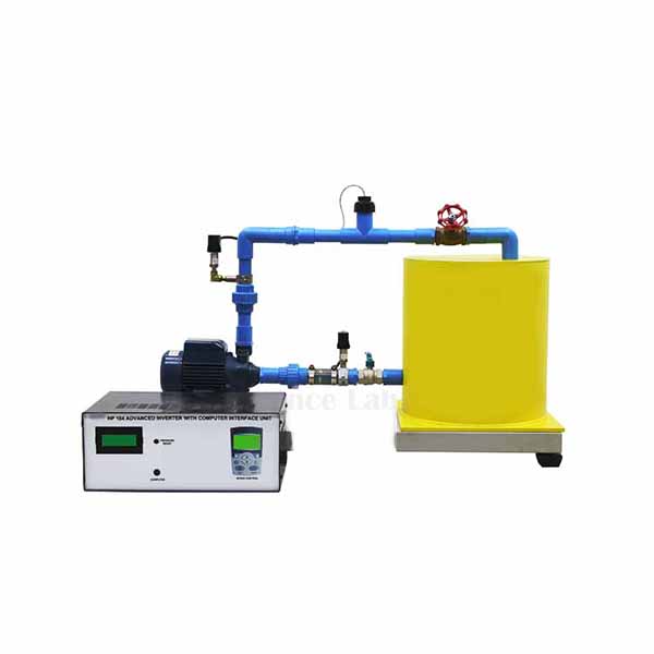
Computerized Gear Pump Test Rig
Computerized Gear Pump Test Rig (Product Code: SLE/MCE/47) is a bench-top positive displacement pump trainer used to measure gear pump flow, shaft power and efficiency with computer software in fluid mechanics laboratories. Its motor-driven gear pump has a clear acrylic pump head, runs at inverter-controlled speeds up to 1,800 rpm and circulates water from an acrylic reservoir on a stainless steel plinth. It is made by Jain Scientific Equipments Pvt Ltd (ScienceLab), an OEM manufacturer, at its own factory in Ambala, India.
Specifications
| Parameter | Detail |
|---|---|
| Pump type | Gear pump (positive displacement), two meshing gear wheels, no valves |
| Construction | Stainless steel plinth with water reservoir and pipework for continuous circulation; pump head and reservoir in clear acrylic |
| Speed control | Electronic inverter |
| Maximum flow rate | 6.5 L/min (typical) |
| Maximum head | 25 m |
| Maximum pump speed | 1,800 rpm |
| Motor | 250 W, 230 V, 1 phase |
| Parameters shown in software | Flow rate, motor shaft power, pump speed, pump efficiency, volumetric efficiency |
| Instrumentation | Sensor conditioning electronics with readings displayed on computer software |
| Dimensions | 670 x 590 x 750 mm |
| Weight | Approx. 50 kg |
| Product code | SLE/MCE/47 |
| Manufacturer | Jain Scientific Equipments Pvt Ltd (ScienceLab) — OEM |
| Country of origin | India (made in Ambala, Haryana) |
What Is the Gear Pump Test Rig Used For?
Gear pumps move oil in hydraulic power packs, lubrication systems and fuel transfer because they deliver a fixed volume per revolution and cope well with high-viscosity fluids. Inside this rig, one gear is driven and the other turns in mesh with it; liquid is carried round in the spaces between consecutive teeth and forced out as the teeth re-engage, all clearly visible through the acrylic pump head.
Students set a series of speeds on the inverter and follow the software as it logs flow rate, motor shaft power, pump speed and the two efficiencies at each operating point. The results show classic positive displacement behaviour: flow stays close to proportional to speed, while volumetric efficiency reveals how much liquid leaks back internally. It is compact engineering educational equipment in India's mechanical labs, and its output is noticeably smoother than a reciprocating pump's.
What to Specify When Ordering
- Whether a computer for the display software should be included, or will be provided by your laboratory.
- Electrical supply at the bench: 230 V, single phase for the 250 W motor.
- Number of rigs for the student groups in each practical session.
OEM Manufacturer
Jain Scientific Equipments Private Limited, which trades as ScienceLab, is the OEM (original equipment manufacturer) of the Computerized Gear Pump Test Rig. The stainless steel plinth, acrylic reservoir and pump head, and pipework are made and assembled at the company's own licensed factory at Saha, Ambala, Haryana, India.
Colleges, dealers and importers therefore get quotations, support and replacement acrylic parts from the manufacturer itself — ask us when you need them. Details of the company are on the ScienceLab company profile.
Related Fluid Mechanics Equipment
Other pump trainers for comparing positive displacement and rotodynamic machines:
- Computerized Reciprocating Pump Test Apparatus — a piston pump rig that shows the pulsating flow a gear pump avoids.
- Gear Pump — an oil gear pump for use with a positive displacement pump module.
- Vane Pump — a balanced vane pump, another fixed-displacement design.
- Axial Flow Pump Test Rig — a high-flow, low-head rotodynamic pump for contrast.
More pump and hydraulics trainers are in the Fluid Mechanics category.
Frequently Asked Questions
What does the Computerized Gear Pump Test Rig measure?
The Computerized Gear Pump Test Rig shows flow rate, motor shaft power, pump speed, pump efficiency and volumetric efficiency on its computer software, using sensor conditioning electronics built into the rig.
What is the maximum performance of the gear pump?
The Computerized Gear Pump Test Rig delivers a typical maximum flow rate of 6.5 L/min and a maximum head of 25 m, with a maximum pump speed of 1,800 rpm from its 250 W, 230 V single-phase motor.
Can students see the gears working?
Yes. On the Computerized Gear Pump Test Rig, both the pump head and the water reservoir are made from clear acrylic, so students can watch the meshing gears carry water around the casing while the rig is running.
Why does the gear pump have no valves?
The pump in the Computerized Gear Pump Test Rig is a positive displacement gear pump: liquid trapped between the teeth is carried round and pushed out as the gears mesh, so no valves are needed and it can deliver against high pressures.
Is a computer supplied with the rig?
The Computerized Gear Pump Test Rig displays its readings on computer software. Whether a computer is included in the supply should be confirmed at quotation, so please state your requirement on the contact page.
Who manufactures the Computerized Gear Pump Test Rig?
The Computerized Gear Pump Test Rig is manufactured by Jain Scientific Equipments Pvt Ltd (ScienceLab), the OEM, at its own factory in Ambala, Haryana, India, and is supplied factory-direct to colleges, dealers and importers.
Request a Quote
For a quotation on the Computerized Gear Pump Test Rig (SLE/MCE/47), write to us on the contact page or add it to the enquiry cart. The manufacturer quotes directly for laboratories in India and international markets.
Last updated: 24 September 2026

Submersible Pump Test Rig
Submersible Pump Test Rig (Product Code: SLE/MCE/48) is a variable-speed pump test set-up used to determine the head, flow and speed characteristics of a submersible pump in mechanical engineering and polytechnic laboratories. It handles up to 70 lpm and 7 m head, with a suction vacuum gauge, a delivery pressure gauge, a proximity-sensor RPM indicator and a measuring tank for timed flow readings. It is made by Jain Scientific Equipments Pvt Ltd (ScienceLab), an OEM manufacturer, at its own factory in Ambala, India.
Specifications
| Parameter | Detail |
|---|---|
| Pump | Self-priming submersible pump |
| Speed | Variable |
| Drive (as listed) | DC motor with thyristor-controlled DC drive; an asynchronous motor with frequency converter is also described — confirm the drive type at quotation |
| Maximum flow rate | 70 lpm |
| Maximum head | 7 m |
| Power rating | 0.75 kW |
| Head adjustment | Ball valve on the outlet side |
| Pressure measurement | Vacuum gauge/sensor on the suction line; pressure gauge/sensor on the delivery line |
| Speed measurement | RPM indicator with proximity sensor |
| Flow measurement | Measuring tank and stopwatch |
| Power supply | 230 V, 1 phase, 50 Hz |
| Dimensions | 1000 x 500 x 700 mm |
| Weight | Approx. 80 kg |
| Product code | SLE/MCE/48 |
| Manufacturer | Jain Scientific Equipments Pvt Ltd (ScienceLab) — OEM |
| Country of origin | India (made in Ambala, Haryana) |
What Is the Submersible Pump Test Rig Used For?
Submersible pumps are the workhorses of borewells, sumps and dewatering jobs, and engineers need to know how their delivery changes with head and speed. On this rig students close the outlet ball valve in steps to raise the head, and at each setting record suction vacuum, delivery pressure, pump speed and the time taken to fill a known volume in the measuring tank.
Repeating the series at several motor speeds produces a family of head-flow curves, and comparing them shows how flow and head scale with rotational speed. Total head is found by combining the delivery pressure and suction vacuum readings. For colleges building a pump laboratory in India, it is a practical, mid-sized piece of lab equipment for college practicals that runs on a single-phase supply.
What to Specify When Ordering
- The drive arrangement you require, since both a thyristor-controlled DC drive and a frequency converter are described for this rig.
- Whether you prefer gauges or electronic sensors for the suction and delivery pressure readings.
- Whether a stopwatch should be supplied for the measuring-tank flow readings.
- Quantity and delivery location.
OEM Manufacturer
The Submersible Pump Test Rig is produced by Jain Scientific Equipments Private Limited under its ScienceLab brand, and the company is the OEM (original equipment manufacturer) of the rig. The frame, tank, pipework and instrument panel are made and assembled at its own licensed factory at Saha, Ambala, Haryana, India.
Because the rig is configured by its maker, questions on the drive, gauges or sensors are answered first-hand, and spares or additional units can be requested from the same team — ask us. Engineering colleges, dealers and importers are supplied factory-direct; more on the ScienceLab company profile.
Related Fluid Mechanics Equipment
Other pump trainers and a timing aid for the same laboratory:
- Variable Speed Series And Parallel Pumps — centrifugal pumps run singly, in series and in parallel.
- Axial Flow Pump Test Rig — a high-flow, low-head pump for comparing characteristics.
- Multi Pump Test Rig — a three-head pump for studying counter pressure and flow.
- Bench Stopwatch — times the measuring tank fill for flow rate.
See the full Fluid Mechanics category for more pump test rigs.
Frequently Asked Questions
What does the Submersible Pump Test Rig measure?
The Submersible Pump Test Rig measures suction vacuum on the inlet line, delivery pressure on the outlet line and pump speed with a proximity-sensor RPM indicator, while flow rate is found with the measuring tank and a stopwatch.
What are the maximum flow and head?
The Submersible Pump Test Rig is rated for a maximum flow rate of 70 lpm and a maximum head of 7 m, with a power rating of 0.75 kW on a 230 V, single-phase, 50 Hz supply.
How is the pump speed varied?
The Submersible Pump Test Rig has a variable-speed drive. Its description lists a DC motor with a thyristor-controlled DC drive and also an asynchronous motor with a frequency converter, so please confirm the drive arrangement when you request a quotation.
How is the pump head changed during a test?
On the Submersible Pump Test Rig, a ball valve on the outlet side is used to adjust the head. Closing it in steps raises the delivery pressure and reduces flow, giving the points needed for a head-flow curve.
How big is the Submersible Pump Test Rig?
The Submersible Pump Test Rig measures 1000 x 500 x 700 mm and weighs about 80 kg, so it fits in a standard pump or hydraulics laboratory with access to a 230 V, single-phase socket.
Who manufactures the Submersible Pump Test Rig?
The Submersible Pump Test Rig is manufactured by Jain Scientific Equipments Pvt Ltd (ScienceLab), the OEM, at its own factory in Ambala, Haryana, India, and quotations come directly from the manufacturer.
Request a Quote
To get a quotation for the Submersible Pump Test Rig (SLE/MCE/48), send your requirements through the contact page or add it to the enquiry cart. The manufacturer quotes directly for buyers in India and international markets.
Last updated: 24 September 2026
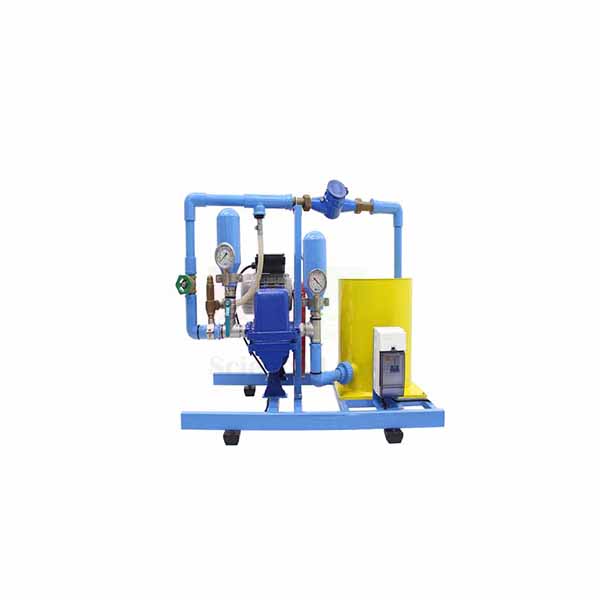
Computerized Reciprocating Pump Test Apparatus
Computerized Reciprocating Pump Test Apparatus (Product Code: SLE/MCE/49) is a piston pump test unit used to record p-V diagrams and pump characteristics on a PC in fluid mechanics and hydraulic machines laboratories. A variable-speed piston pump runs in a transparent housing on a closed water circuit, with an air vessel, a crank angle sensor and pressure sensors in the cylinder and at the outlet. It is made by Jain Scientific Equipments Pvt Ltd (ScienceLab), an OEM manufacturer, at its own factory in Ambala, India.
Specifications
| Parameter | Detail |
|---|---|
| Pump | Piston pump in a transparent housing, variable speed via frequency converter |
| Piston pump speed | 30 to 180 rpm |
| Maximum flow rate | 135 L/h |
| Maximum head | 40 m |
| Drive motor power | 180 W |
| Gear transmission ratio | 1:7.5 |
| Water circuit | Closed circuit with water tank and air vessel to damp pressure pulsation |
| Flow and head adjustment | Needle valve and overflow valve |
| Cylinder pressure | 0 to 5 bar |
| Outlet pressure | 0 to 5 bar |
| Crank angle | 0 to 360°, angle sensor on the piston rod |
| Flow rate measurement | 0.2 to 6 L/min |
| Data acquisition | Microprocessor-based measuring technique in a protective housing; values sent to a PC via USB and analysed with the software included |
| Power supply | 230 V, 50 Hz, 1 phase (230 V, 60 Hz, 1 phase and 120 V, 60 Hz, 1 phase also listed) |
| Dimensions | 670 x 590 x 740 mm |
| Weight | Approx. 49 kg |
| Product code | SLE/MCE/49 |
| Manufacturer | Jain Scientific Equipments Pvt Ltd (ScienceLab) — OEM |
| Country of origin | India (made in Ambala, Haryana) |
What Is the Reciprocating Pump Test Apparatus Used For?
Reciprocating pumps deliver high pressure at low flow — think of pressure washers, dosing systems and boiler feed — but their output comes in pulses. This apparatus makes the full pumping cycle measurable: the angle sensor on the piston rod gives the cylinder volume at every instant, and the cylinder pressure sensor records the matching pressure, so the software can draw the intake and discharge strokes as a p-V diagram.
Students watch the piston through the transparent housing, then use the needle and overflow valves to set different flow rates and heads and compare how the diagram changes. Comparing the pulsating cylinder pressure with the outlet pressure trace shows how the air vessel smooths the delivery. The USB link and included software make it a straightforward piece of computer-linked engineering lab equipment in India for both lab classes and project reports.
What to Specify When Ordering
- Mains supply: 230 V, 50 Hz is standard; 230 V, 60 Hz and 120 V, 60 Hz single-phase versions are also listed.
- Whether a PC should be supplied to run the included software, or your laboratory will provide one with a USB port.
- Quantity of units and the delivery location.
OEM Manufacturer
Jain Scientific Equipments Private Limited, the company behind the ScienceLab name, is the OEM (original equipment manufacturer) of the Computerized Reciprocating Pump Test Apparatus. It is registered as a private limited company under CIN U29309HR2020PTC087597, and the apparatus is assembled at premises covered by Factory Licence AMB-ONLINE-CHD-J-414 at 449, HSIIDC Industrial Area, Saha, Ambala, Haryana.
For buyers this means one accountable source: the maker quotes the unit, dispatches it and deals with any later need for sensors, seals or software help — simply ask us. Universities, polytechnics, dealers and importers in India and international markets are served factory-direct; see the ScienceLab company profile.
Related Fluid Mechanics Equipment
Pump trainers that pair well with p-V studies of a piston pump:
- Computerized Gear Pump Test Rig — a rotary positive displacement pump with a much smoother output.
- Multi Pump Test Rig — a three-head stroke-adjustable pump for flow and counter pressure tests.
- Submersible Pump Test Rig — a rotodynamic pump for contrasting head-flow behaviour.
- Variable Speed Series And Parallel Pumps — centrifugal pumps in single, series and parallel operation.
The Fluid Mechanics category has the rest of the pump and turbine range.
Frequently Asked Questions
How does the Computerized Reciprocating Pump Test Apparatus produce a p-V diagram?
The Computerized Reciprocating Pump Test Apparatus measures piston rod position with an angle sensor to find cylinder volume, and cylinder pressure with a separate sensor. Both are sent to a PC via USB, where the included software plots the p-V diagram.
What is the air vessel for?
On the Computerized Reciprocating Pump Test Apparatus, the air vessel damps the pulsating pressure curve produced by the piston pump. Comparing outlet pressure readings with this damping in action shows students why air vessels are fitted to reciprocating pump installations.
What are the pump's performance figures?
The Computerized Reciprocating Pump Test Apparatus has a piston pump speed of 30 to 180 rpm, a maximum flow rate of 135 L/h and a maximum head of 40 m, driven by a 180 W motor through a 1:7.5 gear transmission.
What are the measuring ranges?
The Computerized Reciprocating Pump Test Apparatus measures cylinder pressure from 0 to 5 bar, outlet pressure from 0 to 5 bar, crank angle from 0 to 360° and flow rate from 0.2 to 6 L/min.
Is software included?
Yes. The Computerized Reciprocating Pump Test Apparatus is supplied with software for analysing the measured values sent over USB. Whether a PC is included should be confirmed at quotation through the contact page.
Who manufactures the Computerized Reciprocating Pump Test Apparatus?
The Computerized Reciprocating Pump Test Apparatus is manufactured by Jain Scientific Equipments Pvt Ltd (ScienceLab), the OEM, at its own factory in Ambala, Haryana, India, and it is supplied factory-direct to institutions, dealers and importers.
Request a Quote
Send an enquiry for the Computerized Reciprocating Pump Test Apparatus (SLE/MCE/49) via the contact page, or add it to the enquiry cart with your preferred power supply. Quotations come directly from the manufacturer.
Last updated: 24 September 2026
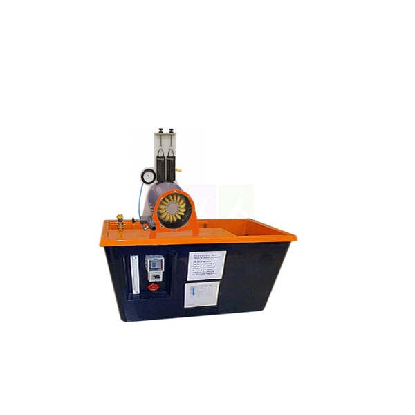
Pelton Turbine Test Rig
Pelton Turbine Test Rig (Product Code: SLE/MCE/50) is an impulse turbine test unit used to measure torque, speed and power of a Pelton wheel at different nozzle settings in hydraulic machines laboratories. A 123 mm wheel with 16 buckets turns under a transparent cover, driven by a needle-controlled nozzle and loaded by a band brake read on spring balances. It is made by Jain Scientific Equipments Pvt Ltd (ScienceLab), an OEM manufacturer of fluid mechanics lab equipment in India, at its own factory in Ambala.
Specifications
| Parameter | Detail |
|---|---|
| Turbine type | Pelton (impulse) wheel; jet deflected by approx. 180° in the buckets |
| Pelton wheel diameter | 123 mm |
| Number of buckets | 16 |
| Nozzle | Adjustable nozzle needle to change the cross-section and flow rate |
| Brake power | 10 W |
| Torque measurement | Band brake with spring balances; force balance range 0 to 20 N x 0.2 N |
| Speed | 0 to 2000 rpm, non-contact speed sensor |
| Pressure gauge range | 0 to 25 m H2O |
| Viewing | Transparent cover over the wheel and nozzle |
| Power required | 230 V, 50 Hz, 1 phase |
| Dimensions | 1000 x 800 x 1200 mm |
| Weight | Approx. 90 kg |
| Product code | SLE/MCE/50 |
| Manufacturer | Jain Scientific Equipments Pvt Ltd (ScienceLab) — OEM |
| Country of origin | India (made in Ambala, Haryana) |
What Is the Pelton Turbine Test Rig Used For?
Pelton wheels are chosen for high-head, low-flow hydro sites, and their operating principle is easy to see on this rig. The water jet is accelerated in the nozzle, strikes the buckets tangentially and is turned back by about 180°, handing its momentum to the wheel. Through the transparent cover students can watch the jet split in each bucket as the needle opens or closes the nozzle.
A standard test holds the nozzle setting constant while the band brake is tightened step by step; the spring balance difference gives brake force, the non-contact sensor gives speed, and the product of torque and speed gives brake power. Plotting power and torque against speed shows the peak near half the jet velocity, and repeating at other needle positions shows part-load behaviour. The 0.2 N resolution of the force balance helps students capture small changes at light load.
OEM Manufacturer
ScienceLab is how Jain Scientific Equipments Private Limited trades, and the company is the OEM (original equipment manufacturer) of the Pelton Turbine Test Rig. The wheel housing, nozzle assembly, brake arrangement and frame are made at its own licensed factory at Saha, Ambala, Haryana, India, and each rig leaves the factory ready for laboratory installation.
Institutions, dealers and importers buy direct from the manufacturer, so replacement brake bands, spring balances or a spare nozzle needle can be requested from the people who built the rig — just ask us. Find out more on the ScienceLab company profile.
Related Fluid Mechanics Equipment
Impulse and reaction turbine equipment that complements this rig:
- Impact of a Jet Apparatus — measures jet force on flat, curved and hemispherical targets, the theory behind Pelton buckets.
- Demonstration Pelton Turbine — a smaller Pelton unit for introductory demonstrations.
- Pelton Wheel (Turbine) — an impulse turbine with a variable spear jet and viewing window.
- Demonstration Francis Turbine — a reaction turbine for comparing the two turbine families.
Visit the Fluid Mechanics category for more turbines, pumps and flow apparatus.
Frequently Asked Questions
What does the Pelton Turbine Test Rig measure?
The Pelton Turbine Test Rig measures brake force on spring balances with a 0 to 20 N x 0.2 N range, wheel speed from 0 to 2000 rpm with a non-contact sensor, and water pressure on a 0 to 25 m H2O gauge.
How is the water flow to the wheel controlled?
On the Pelton Turbine Test Rig, the nozzle needle is adjusted to change the nozzle cross-section and therefore the flow rate. This lets students compare turbine performance at full and part flow with the same wheel.
What size is the Pelton wheel?
The Pelton Turbine Test Rig uses a Pelton wheel of 123 mm diameter with 16 buckets. The buckets deflect the water jet by approximately 180°, transferring the impulse of the jet to the wheel.
What is the brake power of the rig?
The Pelton Turbine Test Rig is specified with a brake power of 10 W. Brake power is calculated from the band brake torque, found from the spring balance readings, and the wheel speed measured by the non-contact sensor.
What supplies does the Pelton Turbine Test Rig need?
The Pelton Turbine Test Rig requires a 230 V, 50 Hz, single-phase power supply. The water supply arrangement for your laboratory should be confirmed at quotation, so describe your set-up on the contact page.
Who manufactures the Pelton Turbine Test Rig?
The Pelton Turbine Test Rig is manufactured by Jain Scientific Equipments Pvt Ltd (ScienceLab), the OEM, at its own factory in Ambala, Haryana, India, and quotations are issued directly by the manufacturer.
Request a Quote
Request a quotation for the Pelton Turbine Test Rig (SLE/MCE/50) through the contact page or the enquiry cart. The manufacturer quotes directly for single rigs and multi-unit laboratory orders in India and international markets.
Last updated: 24 September 2026
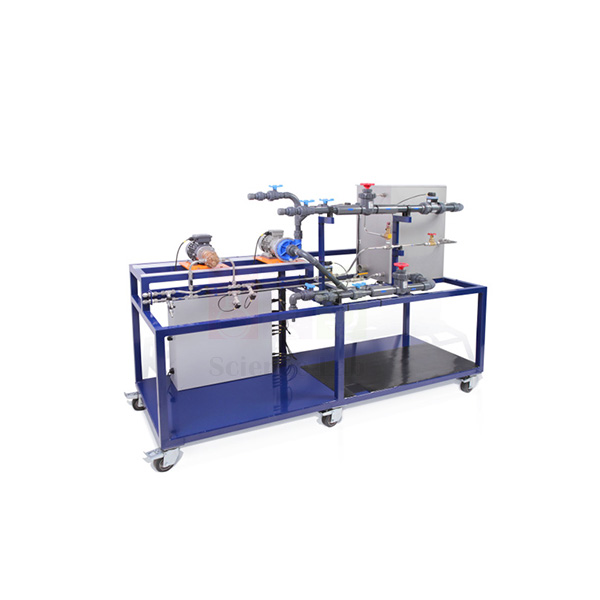
Multi Pump Test Rig
Multi Pump Test Rig (Product Code: SLE/MCE/51) is a pump trainer used to examine a three-head multi pump and the effect of counter pressure on flow rate and mixing ratio in fluid mechanics and process engineering laboratories. Each head has its own stroke adjustment and overflow valve, draws from a shared 60 L feed tank and delivers up to 18 L/h into a scaled measuring tank. It is made by Jain Scientific Equipments Pvt Ltd (ScienceLab), an OEM manufacturer, at its own factory in Ambala, India.
Specifications
| Parameter | Detail |
|---|---|
| Pump | Multi pump with 3 heads |
| Flow rate | 3 x 0 to 18 L/h |
| Stroke rate | 1 x 0 to 100 strokes/min, common to all 3 heads, set at the switch box |
| Stroke length | Individually adjustable for each head |
| Counter pressure | Three overflow valves, one per head; adjustable pressure range 2 to 6 bar |
| Maximum head | Approx. 10 m |
| Maximum suction head | Approx. 3 m |
| Delivery-side pressure | 3 x 0 to 10 bar |
| Intake-side pressure | 3 x -1 to 0 bar |
| Feed tank | 60 L (1 tank) |
| Flow measuring tank | 5 L volumetric tank with scale; level 3 x 0 to 20 cm |
| Power supply | 230 V, 50 Hz, 1 phase |
| Dimensions | 1250 x 500 x 950 mm |
| Weight | Approx. 90 kg |
| Product code | SLE/MCE/51 |
| Manufacturer | Jain Scientific Equipments Pvt Ltd (ScienceLab) — OEM |
| Country of origin | India (made in Ambala, Haryana) |
What Is the Multi Pump Test Rig Used For?
In water treatment, chemical dosing and food processing, several liquids often have to be pumped in a fixed proportion, and multi-head pumps sharing one drive are a common way to do it. This rig lets students test how well that proportion holds. Each head carries water from the feed tank into its own scaled tank, so the delivered volume of every head can be read at the same time.
Students first set a common stroke rate at the switch box and trim the stroke of each head to reach a chosen ratio. They then raise the counter pressure on one head with its overflow valve, watch the delivery and intake manometers, and see how its flow — and therefore the mixing ratio — drifts. As lab equipment for technical institutes, it gives students a clear, hands-on link between pump theory and real dosing practice.
What to Specify When Ordering
- Electrical supply: 230 V, 50 Hz, single phase.
- Floor or bench space for the 1250 x 500 x 950 mm unit, approx. 90 kg.
- Confirmation of the manometer arrangement on the intake and delivery sides for your syllabus.
- Number of rigs and delivery location.
OEM Manufacturer
Jain Scientific Equipments Private Limited, operating as ScienceLab, is the OEM (original equipment manufacturer) of the Multi Pump Test Rig. The frame, feed and measuring tanks, pipework and switch box installation are completed at the company's own licensed factory at Saha, Ambala, Haryana, India.
Since the rig is supplied by its maker, the same team handles your quotation, any later request for spare overflow valves or manometers, and repeat orders for extra benches — ask us. Colleges, training institutes, dealers and importers are supplied factory-direct; visit the ScienceLab company profile.
Related Fluid Mechanics Equipment
Other positive displacement and pump trainers, plus a simple volume check:
- Computerized Reciprocating Pump Test Apparatus — follows a single piston stroke on a p-V diagram.
- Computerized Gear Pump Test Rig — a rotary positive displacement pump with software-logged efficiencies.
- Submersible Pump Test Rig — a rotodynamic pump for contrasting flow behaviour.
- Glass Measuring Cylinder — for cross-checking small delivered volumes.
The Fluid Mechanics category lists every pump and hydraulics trainer in the range.
Frequently Asked Questions
What does the Multi Pump Test Rig demonstrate?
The Multi Pump Test Rig demonstrates how a pump with three heads behaves, and in particular how counter pressure set on each head affects its flow rate and the mixing ratio between the heads.
How are the three pump heads adjusted?
On the Multi Pump Test Rig, a common stroke rate of 0 to 100 strokes per minute is set for all three heads at the switch box, while the stroke of each head is adjusted individually. Three overflow valves set counter pressure between 2 and 6 bar.
How is the flow of each head measured?
Each head of the Multi Pump Test Rig delivers water from the 60 L feed tank into a tank with a scale, and the level readings of 0 to 20 cm give the volume pumped. Each head delivers from 0 to 18 L/h.
What pressure ranges do the manometers cover?
The Multi Pump Test Rig measures delivery-side pressure from 0 to 10 bar and intake-side pressure from -1 to 0 bar for each of its three heads, so students can relate flow changes directly to the pressures acting on each head.
What are the size and power requirements?
The Multi Pump Test Rig measures 1250 x 500 x 950 mm, weighs approximately 90 kg and runs on a 230 V, 50 Hz, single-phase supply. Its maximum head is approximately 10 m and maximum suction head approximately 3 m.
Who manufactures the Multi Pump Test Rig?
The Multi Pump Test Rig is manufactured by Jain Scientific Equipments Pvt Ltd (ScienceLab), the OEM, at its own factory in Ambala, Haryana, India, and it is supplied factory-direct with quotations from the manufacturer.
Request a Quote
For a quotation on the Multi Pump Test Rig (SLE/MCE/51), contact us through the contact page or add it to the enquiry cart. Quotations are issued directly by the manufacturer to institutions, dealers and importers.
Last updated: 24 September 2026
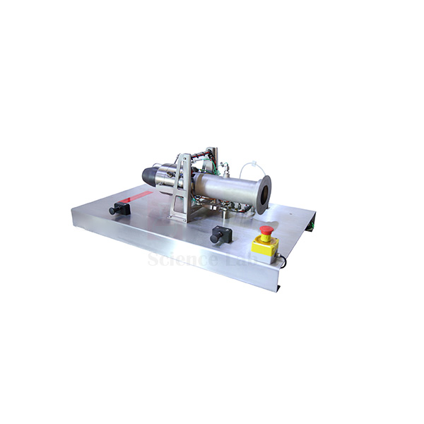
Axial Flow Turbine test bed
Axial Flow Turbine test bed (Product Code: SLE/MCE/52) is a small gas turbine engine test bed used to measure thrust and air mass flow and to study turbine engine operation in engineering and propulsion laboratories. Mechanical and aeronautical engineering departments use it to run an engine with a single-stage radial compressor and a single-stage, low-mass axial flow turbine, producing a typical thrust of 200 N. It is supplied by Jain Scientific Equipments Pvt Ltd (ScienceLab), Ambala, India.
Specifications
| Parameter | Detail |
|---|---|
| Thrust | 200 N typical |
| Air mass flow | 450 g/s |
| Engine speed | 105,000 rpm typical |
| Exhaust gas temperature | 800°C typical |
| Compressor type | Single-stage radial |
| Turbine type | Single-stage, low-mass axial flow |
| Ignition system | Glow plug |
| Engine mount | Single pivot point, enabling accurate thrust measurement |
| Air intake | Custom-fabricated frontal duct replaces the standard inlet so air mass flow rate can be measured accurately |
| Engine control | Electronic pre-programmed controller supervises the engine constantly for safe operating conditions |
| Support systems | No external lubrication system; no external battery or charger needed |
| Frame | Sturdy metal frame holding the engine firmly |
| Safety screen | Tough, transparent polycarbonate |
| Optional stand | Floor-standing frame housing the unit with its fuel tank and electronic console |
| Dimensions | 880 x 510 x 1185 mm |
| Weight | 150 kg (approx.) |
| Product code | SLE/MCE/52 |
| Supplied by | Jain Scientific Equipments Pvt Ltd (ScienceLab), Ambala, India |
What Is the Axial Flow Turbine Test Bed Used For?
The test bed lets students run a real gas turbine and connect what they measure with the Brayton cycle and turbomachinery theory. Air drawn through the frontal duct is compressed by the radial stage, burned, and expanded through the axial flow turbine, which drives the compressor while the exhaust produces thrust. Because the engine pivots on a single mounting point, the reaction can be measured as thrust, and comparing thrust with air mass flow gives a practical feel for jet propulsion performance.
The typical figures of 105,000 rpm and 800°C exhaust temperature give a vivid context for discussing rotor stresses and turbine blade materials. Always run the engine behind the polycarbonate screen, keep the exhaust path clear, and follow your institution's rules on fuel storage, ventilation and hearing protection. As engineering lab equipment in India for colleges with aeronautical or thermal engineering streams, it turns a lecture topic into a live experiment.
What to Specify When Ordering
- Whether the optional floor-standing frame for the unit, fuel tank and electronic console is required
- Installation space for the 880 x 510 x 1185 mm, 150 kg unit
- The fuel the engine uses and its handling on your site — confirm with us before ordering
- Quantity and delivery destination
Supplier
The Axial Flow Turbine test bed is supplied by Jain Scientific Equipments Private Limited, the Ambala company that trades as ScienceLab. The company sources the test bed for engineering colleges, aeronautical institutes, dealers and importers, and handles the quotation, packing and dispatch to India and international markets.
Questions about the controller, the optional stand or parts can be sent to the same team, and we will check what can be arranged. Company details are on the ScienceLab profile page.
Related Fluid Mechanics Equipment
These rigs support the same turbomachinery teaching sequence, from water turbines to other gas turbine and compressor benches:
- Axial Flow Pump Test Rig — the pumping counterpart of axial flow turbomachinery.
- Pelton Turbine Test Rig — an impulse water turbine for contrasting hydraulic and gas turbines.
- Turbojet Engine Test Bench — an alternative jet engine bench for propulsion experiments.
- Two Shaft Gas Turbine — extends the study to a gas generator driving a separate power turbine.
- Rotary Air Compressor Test Bench — looks at the compression stage on its own.
More rigs are listed under Fluid Mechanics.
Frequently Asked Questions
What does the Axial Flow Turbine test bed measure?
The Axial Flow Turbine test bed is designed for accurate thrust measurement through its single-pivot engine mount, and its custom frontal duct allows the air mass flow rate to be measured. Typical values are 200 N thrust and 450 g/s air mass flow.
Does the Axial Flow Turbine test bed need an external battery or lubrication system?
No. The Axial Flow Turbine test bed needs neither an external lubrication system nor an external battery and charger. An electronic pre-programmed controller supervises the engine constantly to keep operating conditions safe.
Is a stand available for the Axial Flow Turbine test bed?
Yes, an optional floor-standing frame is available for the Axial Flow Turbine test bed. It houses the unit together with its fuel tank and electronic console, keeping the set-up compact in a teaching laboratory. State on your enquiry if you need it.
What safety features does the Axial Flow Turbine test bed have?
The Axial Flow Turbine test bed has a tough, transparent polycarbonate safety screen, a sturdy metal frame that holds the engine firmly and an electronic controller supervising the engine. Laboratories should still apply their own rules for fuel, ventilation and noise.
Who supplies the Axial Flow Turbine test bed?
The Axial Flow Turbine test bed is supplied by Jain Scientific Equipments Pvt Ltd (ScienceLab) of Ambala, Haryana, India. The company quotes, packs and ships it to engineering institutions, dealers and importers in India and international markets.
Is a calibration certificate available for the Axial Flow Turbine test bed?
Calibration-certificate availability for the Axial Flow Turbine test bed, including its thrust measurement, should be discussed with us before ordering. Mention the requirement through the contact page so the quotation can address it.
What should a quotation request for the Axial Flow Turbine test bed include?
A quotation request for the Axial Flow Turbine test bed should give the quantity, whether the optional floor-standing frame is needed, the delivery location and any documents your institution requires, so ScienceLab can reply with a complete quote.
Request a Quote
To request a quote for the Axial Flow Turbine test bed, send your requirements through the ScienceLab contact page or add the product to the enquiry cart. Include quantity, the optional stand and delivery location.
Last updated: 24 September 2026
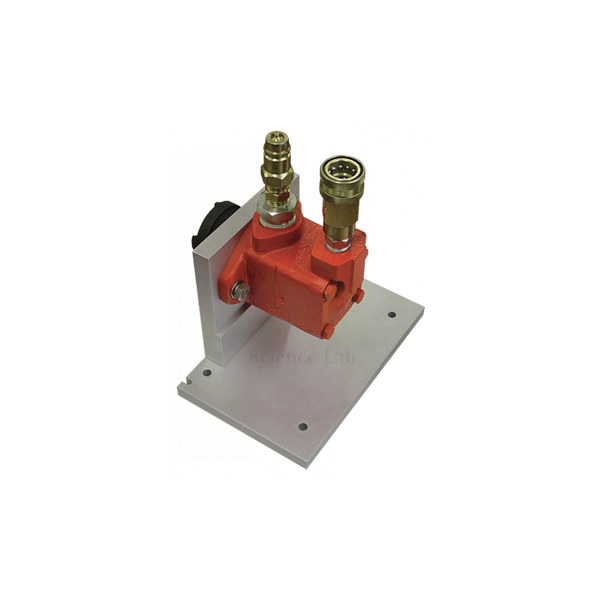
Vane Pump
The Vane Pump (Product Code: SLE/EFM/01) is a fixed displacement, balanced vane pump that delivers a set volume of oil for every full turn of its shaft. It is built for use with the Positive Displacement Pump Module, where students run it for experiments, demonstrations and project work on hydraulic machines. Produced by Jain Scientific Equipments Pvt Ltd (ScienceLab), Ambala, it belongs to our engineering lab equipment for India’s polytechnics, engineering colleges and technical training centres.
Specifications
| Parameter | Detail |
|---|---|
| Pump type | Positive displacement, fixed displacement balanced vane |
| Working fluid | Oil |
| Delivery | A given volume of fluid for each full rotation of the pump shaft |
| Flow direction | Set by pump rotation; tested in one direction, determined by the Universal Dynamometer |
| Connections | Self-sealing, to reduce oil spillage and simplify installation on the pump module |
| For use with | Positive Displacement Pump Module |
| Dimensions | 300 mm x 300 mm x 300 mm (approx) |
| Weight | 9 kg |
Typical Use
Once the pump is mounted on the Positive Displacement Pump Module and coupled to the Universal Dynamometer, students can vary shaft speed and delivery pressure and record how flow, torque and power respond. Because a positive displacement pump moves a fixed volume per revolution, the class can compare the theoretical flow with the measured flow to find volumetric efficiency, and see how internal leakage grows as pressure rises. In a balanced vane design, opposing pressure zones inside the housing help even out the side loads on the rotor, a point worth discussing when comparing it with other pump types.
Among lab equipment for technical institutes, interchangeable pumps like this one let a single test module cover several machines in one term. The self-sealing connections keep oil where it belongs during changeovers, so students can remove and fit the pump without draining the circuit. Wipe connections before fitting, keep the oil clean, and follow the direction of rotation set by the dynamometer.
Manufacturer
Jain Scientific Equipments Private Limited, known to customers by its ScienceLab brand, manufactures teaching equipment in Ambala, Haryana. It holds MSME registration under Udyam UDYAM-HR-01-0003714, and its export consignments move under DGFT Importer-Exporter Code AAECJ8618A. Our company profile has more information.
Related Fluid Mechanics Equipment
Machines and drive units that belong in the same pump-testing programme:
- Universal Dynamometer — drives the pump and reads speed, torque and shaft power
- Gear Pump — a second positive displacement design for side-by-side comparison
- Axial Flow Pump Module — contrasts displacement pumping with a rotodynamic pump
- Reciprocating Compressor — another dynamometer-driven machine for the same lab
View all apparatus in our Fluid Mechanics category.
Frequently Asked Questions
What does the Vane Pump need in order to run?
It is designed for the Positive Displacement Pump Module and is tested in the direction determined by the Universal Dynamometer. Please contact us to confirm what your existing set-up already includes.
Is the Positive Displacement Pump Module part of this item?
This listing covers the vane pump itself. Ask us about the module and drive when you request a quotation.
Which fluid does it pump?
Oil. The exact grade to use is best confirmed with our team before commissioning.
How large and heavy is it?
Approximately 300 mm x 300 mm x 300 mm, weighing 9 kg.
Can the flow direction be reversed?
Pump rotation sets the flow direction, but the pump is tested in one direction only, as determined by the Universal Dynamometer.
What warranty and documentation are provided?
Warranty terms and any test documentation are stated on the quotation; raise specific needs when you enquire.
Do you supply engineering colleges outside India?
Yes. We supply institutions in India and international markets; include the destination in your enquiry.
Request a Quote
Planning a pump-testing lab? Send us your requirements, or add the Vane Pump to the enquiry cart along with the dynamometer and other modules.
Last updated: 24 September 2026
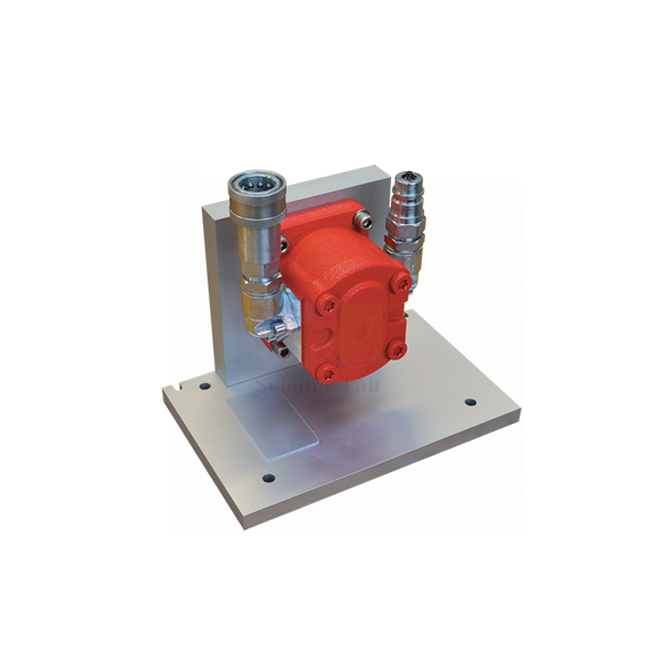
Gear Pump
The Gear Pump (Product Code: SLE/EFM/02) is a positive displacement pump in which a pair of meshing gears carries a fixed volume of oil from inlet to outlet on every full rotation of the shaft. Designed to fit the Positive Displacement Pump Module, it gives students a hands-on way to study one of the simplest and most widely used hydraulic pump designs through experiments, demonstrations and projects. It is manufactured by Jain Scientific Equipments Pvt Ltd (ScienceLab), Ambala, an engineering lab equipment manufacturer serving technical colleges and training institutes.
Specifications
| Parameter | Detail |
|---|---|
| Pump type | Positive displacement gear pump |
| Pumping element | Double gears |
| Working fluid | Oil |
| Delivery | A given volume of fluid for each full rotation of the pump shaft |
| Flow direction | Generally set by gear rotation; test in one direction only, determined by the Universal Dynamometer |
| Connections | Self-sealing, reducing oil spillage and simplifying installation on the pump module |
| For use with | Positive Displacement Pump Module |
Typical Use
Gear pumps are found in lubrication systems, machine-tool hydraulics and mobile equipment, so the experiments carry over directly to what students will see in industry. On the module, the class runs the pump at several speeds, notes how delivered flow follows speed almost in step, and then raises the outlet pressure to observe the torque demand increase and the small drop in flow caused by leakage past the gear teeth. Working out the displacement per revolution from measured data, and comparing it with the value expected from the gear geometry, is a good exercise in engineering estimation.
For TVET and diploma courses that need mechanics lab equipment in India with a clear link to maintenance work, running the gear pump alongside a vane pump on the same module lets learners compare noise, flow smoothness and efficiency between the two designs. The self-sealing connections make that swap quick and tidy. Keep the oil topped up and clean, and never run the pump dry.
Manufacturer
The Gear Pump is produced by Jain Scientific Equipments Private Limited of Ambala, Haryana — the company behind the ScienceLab name — which designs and builds apparatus for engineering, science and vocational teaching. Find out more on the company profile page.
Related Fluid Mechanics Equipment
Apparatus used with, or compared against, the Gear Pump:
- Universal Dynamometer — the drive that sets test direction and measures shaft power
- Vane Pump — an alternative positive displacement pump for the same module
- Two Stage (Series And parallel) — centrifugal pumps that show how rotodynamic machines behave differently
Our full Fluid Mechanics range covers pumps, turbines and flow-measurement apparatus.
Frequently Asked Questions
How does the Gear Pump move oil?
Its double gears trap oil between the teeth and the casing and carry it to the outlet, delivering a given volume for each full rotation of the shaft.
Can it be used on its own?
It is intended for the Positive Displacement Pump Module, driven in the direction set by the Universal Dynamometer. Contact us to check compatibility with your existing equipment.
What are its dimensions and weight?
These are not listed in our current product data; we can provide them with your quotation.
Why are the connections self-sealing?
They reduce oil spillage and make it simpler to install the pump on the module or swap it for another pump.
Which oil should be used?
Please confirm the recommended oil with our team before first use.
What should our purchase enquiry include?
Quantity, whether you already own the module and dynamometer, and the delivery address. We supply institutions in India and international markets.
Request a Quote
To price the Gear Pump for your lab, reach our team or put it in the enquiry cart and send the full list in one go.
Last updated: 24 September 2026
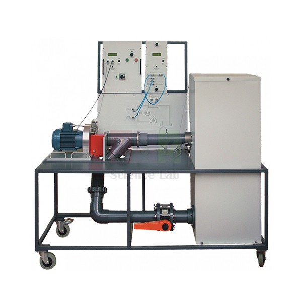
Axial Flow Pump Module
The Axial Flow Pump Module (Product Code: SLE/EFM/03) is a self-contained test rig built around an axial flow pump, mounted in a mobile frame with full instrumentation that includes a digital pressure display. It lets students study and test a common type of rotodynamic pump safely and at a realistic scale, without needing any external water supply. The module is made by Jain Scientific Equipments Pvt Ltd (ScienceLab), Ambala, and is part of the engineering educational equipment we build for colleges in India and abroad.
Specifications
| Parameter | Detail |
|---|---|
| Pump type | Axial flow (rotodynamic) |
| Mounting | Mobile frame |
| Instrumentation | Full instrumentation, including a digital pressure display |
| Speed and flow | Fully variable, for a range of tests |
| Water supply | Own water reservoir; no external water supply needed |
| Drive | Part of the Modular Fluid Power range; connects with the Universal Dynamometer as a common motive-power source |
| Connection plate | Schematic diagram showing the water flow circuit and how the parts of the module connect |
Typical Use
The core experiment is the pump characteristic: at a fixed speed, students throttle the flow in steps, record pressure rise and shaft power at each point, and plot head, power and efficiency against flow rate. Repeating the test at other speeds shows how the whole curve shifts and gives a practical introduction to the pump scaling laws. Axial flow pumps move large volumes against relatively modest heads, so comparing their curves with those of a centrifugal pump helps students understand why each design suits different duties, from drainage and irrigation to cooling-water circuits.
Because the module carries its own reservoir, it can be wheeled into any teaching space as lab equipment for college practicals without plumbing. Sharing one Universal Dynamometer across several Fluid Power modules keeps the cost of a full lab down, and the schematic on the connection plate helps students trace the circuit before they start. Check the reservoir level before each session and drain it for long storage.
Manufacturer
ScienceLab is how Jain Scientific Equipments Private Limited presents its products to schools, colleges and training centres. The company operates from Ambala, Haryana, where it manufactures teaching apparatus including this pump module; details are on our company profile.
Related Fluid Mechanics Equipment
Equipment that builds out a rotodynamic machines lab with this module:
- Universal Dynamometer — the shared drive that supplies and measures shaft power
- Two Stage (Series And parallel) — centrifugal pumps for comparing radial-flow and axial-flow behaviour
- Centrifugal Fan Module — extends rotodynamic testing from water to air
- Vane Pump — a positive displacement contrast to the axial flow design
See the complete Fluid Mechanics collection for more hydraulics apparatus.
Frequently Asked Questions
Does the Axial Flow Pump Module need a water connection?
No. It is self-contained with its own water reservoir.
What drives the pump?
The module is part of the Modular Fluid Power range and connects with the Universal Dynamometer, which acts as a common motive-power source for several modules.
Is the Universal Dynamometer included?
It is listed as a separate product. Tell us whether you already own one when you request a quotation.
What readings are displayed?
The module has full instrumentation including a digital pressure display; the dynamometer adds speed, torque and shaft power.
What are the module’s size, weight and reservoir capacity?
These details are not in our current listing. Our team can confirm them so you can plan floor space.
Is operator training or installation guidance available?
Please discuss your commissioning needs with us at the enquiry stage.
Can it be shipped internationally?
Yes. We supply institutions in India and international markets; include your destination in the enquiry.
Request a Quote
Equipping a fluid machines lab? Contact us with your module list, or add the Axial Flow Pump Module to the enquiry cart for a combined quotation.
Last updated: 24 September 2026
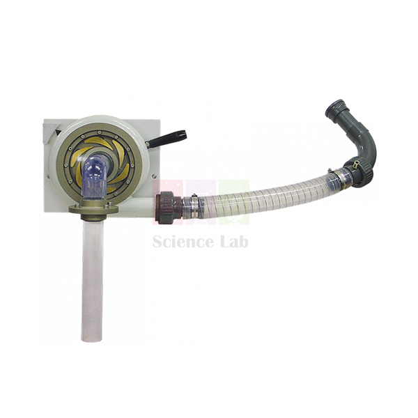
Francis Turbine
The Francis Turbine (Product Code: SLE/EFM/04) is a teaching model of the reaction turbine found in many hydroelectric plants. Adjustable guide vanes control the water entering the machine and direct it at an angle onto the blades of a radial impeller, and a clear viewing window and draft tube let students watch the turbine working as they change the vane setting. It is manufactured by Jain Scientific Equipments Pvt Ltd (ScienceLab), Ambala, a technical educational equipment manufacturer supplying engineering departments and polytechnics.
Specifications
| Parameter | Detail |
|---|---|
| Turbine type | Reaction turbine |
| Moving part | Radial impeller |
| Flow control | Adjustable guide vanes that control the water flow and direct it at an angle to the impeller blades |
| Visibility | Clear viewing window and draft tube |
| Learning focus | How the guide vane setting affects the way the turbine works |
Typical Use
The Francis design is widely used around the world because it adapts to a wide range of applications, which makes it a natural centrepiece for hydraulic machines practicals. A typical session sets the guide vanes to one opening, loads the turbine in stages and records speed, torque and flow to build output and efficiency curves; the vanes are then moved to a new position and the test repeated. Students quickly see that each vane opening has its own best operating point, and why power stations adjust guide vanes rather than simply throttling the supply.
Being a reaction machine, the runner turns under both the pressure and the velocity of the water, unlike an impulse wheel. Watching through the window and down the draft tube, the class can relate swirl and flow pattern to efficiency and discuss how the draft tube recovers energy from the leaving water. For engineering lab equipment in India’s degree and diploma programmes, testing this turbine against a Pelton wheel gives a complete picture of reaction and impulse behaviour.
Manufacturer
Our Francis Turbine is made by Jain Scientific Equipments Private Limited, which trades as ScienceLab and is headquartered in Ambala, Haryana. The firm builds hydraulics, mechanics and science apparatus for teaching laboratories; see the company profile for background.
Related Fluid Mechanics Equipment
Apparatus that complements a turbine study programme:
- Pelton Wheel (Turbine) — the impulse-turbine counterpart for comparison tests
- Universal Dynamometer — measures speed, torque and shaft power on Fluid Power machines (ask us about pairing)
- Cavitation In Venturi — explains the cavitation risk that turbine designers must manage
- Water Turbine with Dynamo Model — a simple hydro-power model for introductory classes
Browse our Fluid Mechanics category for pumps, flumes and flow apparatus.
Frequently Asked Questions
Is the Francis Turbine an impulse or a reaction turbine?
It is a reaction turbine, with a radial impeller as its moving part.
What can students change during a test?
The adjustable guide vanes. Changing their setting alters how much water enters and the angle at which it meets the impeller blades.
Can students see inside while it runs?
Yes, through the clear viewing window and draft tube.
What water supply and loading device does it need?
These requirements are not detailed in our current listing. Please contact us so we can confirm the supply and measurement set-up for your lab.
What are the turbine’s dimensions and rated output?
We can provide size and performance details with your quotation; they are not published on this page.
How is it maintained?
Drain water after use, keep the viewing window clean with a soft cloth, and check that the guide vane mechanism moves freely before each session.
Do you supply universities overseas?
Yes. We serve institutions in India and international markets; share the destination and quantity when you enquire.
Request a Quote
For pricing on the Francis Turbine, send your enquiry or add it to the enquiry cart with any companion apparatus for your hydraulics lab.
Last updated: 24 September 2026
411.jpg)
Pelton Wheel (Turbine)
The Pelton Wheel (Turbine) (Product Code: SLE/EFM/05) is an impulse turbine with tangential flow: a jet of water from a variable spear nozzle strikes a ring of paired buckets and drives the wheel round. A clear viewing window on the side lets students see exactly how the jet and buckets interact. Built by Jain Scientific Equipments Pvt Ltd (ScienceLab), Ambala, it is designed as lab equipment for college and polytechnic hydraulics courses studying high-pressure, low-flow machines.
Specifications
| Parameter | Detail |
|---|---|
| Turbine type | Impulse turbine, tangential flow |
| Inlet | Variable spear jet |
| Buckets | Arranged in pairs to balance the wheel correctly and work efficiently |
| Viewing | Clear viewing window on the side of the turbine |
| Best suited to | Applications with high pressure and low flow |
Typical Use
The variable spear jet is the key teaching control. Moving the spear changes the jet, and with it the velocity of the water hitting the buckets, so students can explore how jet speed, wheel speed and power output relate. A standard exercise records output across a range of wheel speeds at a fixed spear setting and then repeats the run at another setting, revealing that the wheel performs best when its bucket speed is a particular fraction of the jet speed — a result students can compare with impulse-momentum theory.
Watching through the side window, the class sees the jet split by each pair of buckets and turned back on itself, which explains why the buckets are paired: the split keeps side forces balanced and allows the water to leave with little remaining energy. Pelton wheels suit mountain hydro schemes with high heads and modest flows, so for vocational training lab equipment in India this turbine connects classroom theory with real installations. Contrasting it with a Francis reaction turbine rounds off the topic.
Manufacturer
Jain Scientific Equipments Private Limited manufactures the Pelton Wheel at Ambala in Haryana and sells it under the ScienceLab trading name to engineering and science teaching institutions. Learn more on our company profile.
Related Fluid Mechanics Equipment
Apparatus that fits the same turbine and jet-flow lessons:
- Francis Turbine — a reaction turbine to contrast with the impulse principle
- Universal Dynamometer — measures speed, torque and shaft power on Fluid Power machines (confirm pairing with us)
- Pipe Flow And Nozzle Kit — explores how nozzles convert pressure into jet velocity
- Bernoulli’s Theorem — the energy principle behind jet formation
Find more hydraulics apparatus in the Fluid Mechanics range.
Frequently Asked Questions
What type of turbine is the Pelton Wheel?
An impulse turbine with tangential flow, suited to high pressure and low flow.
How is the water jet controlled?
By the variable spear jet at the inlet, which lets students change the velocity of the water striking the buckets.
Why are the buckets in pairs?
Pairing balances the wheel correctly and helps it work efficiently.
What pump or water supply is required?
Supply requirements are not stated in our current listing. Contact us and we will confirm what is needed to run it in your lab.
Are wheel diameter and bucket count specified?
Not on this page; we can share dimensional details on request.
Can a calibration certificate be supplied?
Discuss any certificate or test-record needs with our team before ordering so we can advise.
Can we order it together with other fluid mechanics apparatus?
Yes. One enquiry can cover several items, for delivery within India or to international markets.
Request a Quote
Ask for a Pelton Wheel quotation through our contact page, or save it in the enquiry cart while you finish selecting your turbine lab equipment.
Last updated: 24 September 2026
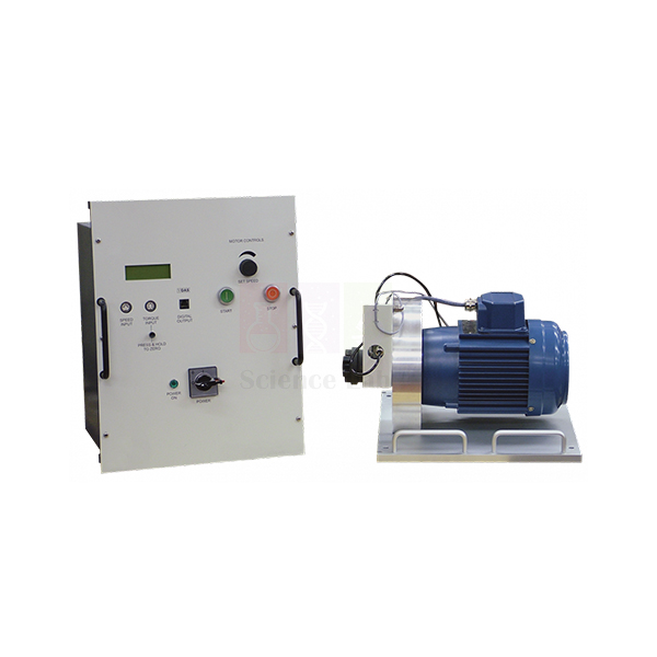
Universal Dynamometer
The Universal Dynamometer (Product Code: SLE/EFM/06) is the shared drive and measuring unit for the Fluid Power machines. It pairs a trunnion-mounted induction motor, which reacts against a strain gauge load cell, with a motor drive and display unit that digitally shows speed, torque and shaft power. Because it couples directly to each machine, students spend their time taking readings rather than fitting belts and pulleys. It is manufactured by Jain Scientific Equipments Pvt Ltd (ScienceLab), Ambala, as part of our test and measuring instrument range for engineering teaching labs.
Specifications
| Parameter | Detail |
|---|---|
| Main parts | Electric dynamometer; motor drive and display unit |
| Dynamometer | Induction motor, trunnion-mounted to move freely against a strain gauge load cell |
| Drive electronics | Variable-speed a.c. inverter drive with signal conditioning |
| Displayed readings | Speed, torque and shaft power (digital) |
| Speed sensing | Inductive sensor on the shaft |
| Torque sensing | Load cell |
| Base plate | Precision-machined, holding the motor and sensors, with location points for accurate, repeatable alignment onto each Fluid Power module |
| Coupling | Jaw-type coupling with a rubber element, common to all Fluid Power machines |
| Controls | Motor stop, start and speed controls on the front of the drive and display unit |
| Instrument power | Outlets on the back supply the instruments provided with the Fluid Power modules |
Typical Use
In a Fluid Power lab the dynamometer is lifted onto whichever module is scheduled for the day — a pump, a compressor or another machine — and dropped onto the base-plate location points so the shaft lines up with the machine’s jaw coupling. Students then set the speed from the front panel and read torque, speed and shaft power directly. Because the motor is trunnion-mounted, the reaction torque on its casing is exactly what the load cell senses, so the displayed torque is the torque delivered to the machine; combining it with the machine’s own flow and pressure readings gives input power, output power and efficiency.
For institutions choosing TVET lab equipment in India, one dynamometer serving many modules is an economical way to build a complete fluid machines laboratory. The instrument outlets on the rear panel mean each module’s gauges draw power from the same unit, cutting down trailing mains leads and keeping the bench tidier and safer. Always press stop before swapping modules, and keep the rubber coupling element in good condition.
Manufacturer
The Universal Dynamometer is built by Jain Scientific Equipments Private Limited in Ambala, Haryana; the company’s products are branded ScienceLab and serve teaching labs at schools, colleges and technical institutes. Read about us on the company profile page.
Related Fluid Mechanics Equipment
Machines whose product data names the Universal Dynamometer as their drive or measuring partner:
- Axial Flow Pump Module — a rotodynamic pump module in the Modular Fluid Power range
- Reciprocating Compressor — the dynamometer measures its speed, torque and absorbed power
- Vane Pump — test direction is set by the dynamometer
- Gear Pump — a second positive displacement pump driven the same way
All hydraulics and fluid machines apparatus is listed in our Fluid Mechanics category.
Frequently Asked Questions
What does the Universal Dynamometer measure?
Shaft speed (by an inductive sensor), shaft torque (by a load cell) and shaft power, all shown on the digital display.
Do I need belts or pulleys to connect it?
No. It drives the Fluid Power machines directly through a jaw-type coupling with a rubber element.
How is alignment kept consistent between modules?
The precision-machined base plate has location points that give accurate, repeatable alignment onto each Fluid Power module.
Can the motor speed be varied?
Yes. The drive and display unit contains a variable-speed a.c. inverter drive, with stop, start and speed controls on the front.
What mains supply and motor rating does it use?
These electrical details are not listed on this page. Please contact us so we can confirm them for your country’s supply.
Is calibration documentation provided for the load cell?
Discuss your calibration or certificate requirements with our team when you enquire.
Do we need one dynamometer per module?
No. It is designed to move between modules, so one unit can serve several machines in turn.
Request a Quote
For a quotation on the Universal Dynamometer on its own or with modules, contact our team or add the items to your enquiry cart. We supply institutions across India and international markets.
Last updated: 24 September 2026
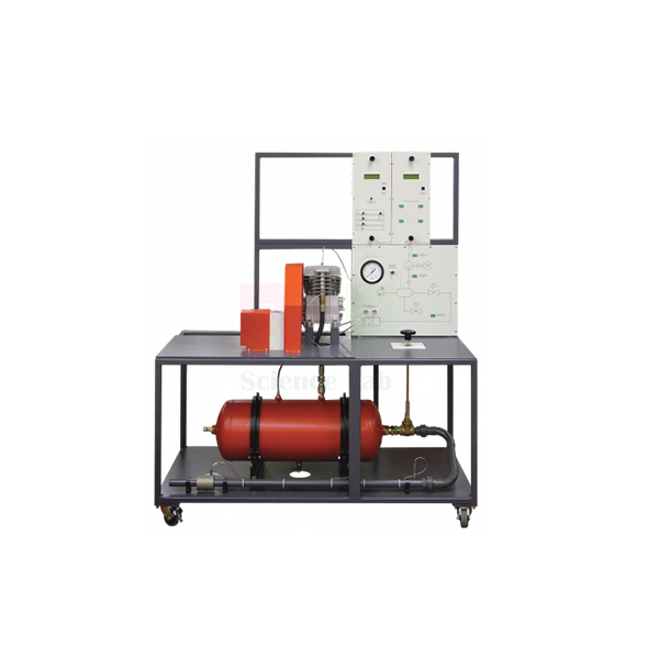
Reciprocating Compressor
The Reciprocating Compressor (Product Code: SLE/EFM/07) is a trolley-mounted test module containing a small compressor, an air receiver and instrumentation, used to show students how a piston compressor turns shaft power into compressed air. A valve and orifice on the receiver outlet let the class set delivery pressure and measure the mass flow of air leaving the system. The module is manufactured by Jain Scientific Equipments Pvt Ltd (ScienceLab), Ambala, as lab equipment for technical institutes, engineering colleges and industrial training centres.
Specifications
| Parameter | Detail |
|---|---|
| Module contents | Small reciprocating compressor, air receiver and instrumentation |
| Mounting | Robust, mobile trolley |
| Air path | Air enters the compressor and is delivered under pressure to the receiver |
| Pressure control | Valve releasing receiver pressure to atmosphere through an orifice; the valve sets receiver pressure and hence flow rate |
| Flow measurement | Orifice for accurate measurement of outlet air mass flow rate |
| Speed | Fully variable up to the maximum allowable for the compressor |
| Power measurement | Speed, torque and power absorbed measured by the separate Universal Dynamometer |
Typical Use
Reciprocating compressors supply the air behind air tools, paint spray equipment, pneumatic actuators and control systems, so this module links directly to what students meet in workshops and plants. In a typical test the compressor runs at a chosen speed while the outlet valve is closed in steps; at each receiver pressure the class records mass flow from the orifice and the power absorbed from the dynamometer. The resulting curves show how the flow the compressor can deliver falls as delivered pressure rises, and let students calculate volumetric efficiency and the power needed per unit of air.
Repeating the series at different speeds shows the effect of running a compressor faster or slower, a practical point for anyone who will later size or operate a plant compressor. As engineering educational equipment for Indian diploma and degree programmes, the trolley mounting lets one module move between rooms. Release receiver pressure fully after each session, keep the orifice clean, and keep hands clear of moving parts while the machine runs.
Manufacturer
This compressor module is produced by Jain Scientific Equipments Private Limited, an Ambala, Haryana manufacturer whose apparatus is sold under the ScienceLab name. The company serves teaching laboratories across engineering and the sciences; visit our company profile to learn more.
Related Fluid Mechanics Equipment
Apparatus that completes a compressor and fluid machines practical:
- Universal Dynamometer — needed to measure speed, torque and power absorbed by the compressor
- Centrifugal Fan Module — a rotodynamic air machine to compare with positive displacement compression
- Calibration of a Pressure Gauge — builds confidence in the pressure readings students rely on
- Vane Pump — a liquid positive displacement machine for the same dynamometer
More modules are listed in the Fluid Mechanics collection.
Frequently Asked Questions
What is included in the Reciprocating Compressor module?
A small compressor, an air receiver and instrumentation, all mounted on a robust mobile trolley.
Is the Universal Dynamometer part of the module?
No. It is a separate unit that measures speed, torque and the power absorbed by the compressor.
How is air flow measured?
Air leaves the receiver through a valve and an orifice; the orifice allows accurate measurement of the outlet air mass flow rate.
How do students change the operating point?
The valve sets the receiver pressure, and hence the flow rate, while compressor speed is fully variable up to its maximum allowable value.
What are the maximum pressure and receiver volume?
These ratings are not published on this page. Please ask our team for the figures before planning experiments.
What warranty applies?
Warranty terms are confirmed on each quotation.
Can you deliver outside India?
Yes. We supply institutions in India and international markets.
Request a Quote
Tell us about your lab through the contact page, or add the Reciprocating Compressor to the enquiry cart, and we will send pricing for the module and any dynamometer you need.
Last updated: 24 September 2026
275.jpg)
Two Stage (Series And parallel)
The Two Stage (Series And parallel) apparatus (Product Code: SLE/EFM/08) is a two-pump centrifugal test rig in which students run each pump alone, or both together in series or in parallel, and measure how the combined system behaves. Each pump has its own motor, speed control, torque load cell and speed sensor, and flow is found from the differential pressure across a Venturi meter. It is manufactured by Jain Scientific Equipments Pvt Ltd (ScienceLab), Ambala, and forms part of our engineering lab equipment for India’s mechanical and civil engineering departments.
Specifications
| Parameter | Detail |
|---|---|
| Pumps | Two centrifugal pumps, working alone, in series or in parallel |
| Drive | Two bearing-mounted motors, one driving each pump independently |
| Per-pump instrumentation | Electronic Motor Drive for speed control, load cell for torque, sensor for pump speed |
| Configuration | Two-way valve selects single, parallel or series operation; each pump has its own inlet valve |
| Water circuit | Integral reservoir → strainers → series of valves → Venturi meter → back to reservoir for re-use |
| Flow measurement | Differential pressure across the Venturi meter |
| Layout | Instrument and control modules fit into a frame above and behind the pumps |
Typical Use
Students usually begin with one pump, plotting head, power and efficiency against flow. They then switch the two-way valve to series and see the heads add at a given flow, before changing to parallel and seeing the flows add at a given head — the two classic results every engineer needs when designing a pumping station or booster system. Because each motor has its own speed control and torque measurement, the pumps can also be run at different speeds to show what happens when mismatched machines share a system.
Closing an inlet valve progressively lets the class see cavitation begin and hear the change in pump noise, giving a vivid lesson in suction conditions. The same rig teaches flow measurement: students convert the Venturi differential pressure into flow rate and compare the result with theory. Since water returns to the reservoir for re-use, water consumption stays low, which makes the rig well suited as lab equipment for college buildings without large drainage facilities. Clean the strainers regularly and refill the reservoir with clean water.
Manufacturer
Jain Scientific Equipments Private Limited, the Ambala, Haryana company behind the ScienceLab brand, makes this rig for teaching laboratories. Its corporate identity number is CIN U29309HR2020PTC087597, and apparatus is produced at the licensed works at 449, HSIIDC Industrial Area, Saha, Ambala, under Factory Licence AMB-ONLINE-CHD-J-414. See our company profile for further details.
Related Fluid Mechanics Equipment
Apparatus that extends the pump, cavitation and Venturi topics covered by this rig:
- Variable Speed Series And Parallel Pumps — an alternative rig for series and parallel pump studies
- Cavitation In Venturi — a closer look at the cavitation students observe here
- Bernoulli’s Theorem — the principle behind Venturi flow measurement
- Axial Flow Pump Module — compares centrifugal and axial flow pump characteristics
Explore the full Fluid Mechanics range.
Frequently Asked Questions
Can the pumps be tested individually?
Yes. Each pump can work alone, and a two-way valve switches the system to series or parallel operation.
How is flow rate measured?
From the differential pressure across the Venturi meter in the delivery line.
Can the two pumps run at different speeds?
Yes. Each is driven by its own bearing-mounted motor with an electronic Motor Drive, a torque load cell and a speed sensor.
Does it need a mains water connection?
The pumps draw from an integral reservoir and the water returns to it for re-use. Please contact us for filling and electrical requirements.
Can students observe cavitation?
Yes. The rig is designed to let students see cavitation as well as study Venturi flow measurement.
What are the footprint and pump ratings?
These are not listed on this page; our team can supply them with a quotation.
What information do you need for an institutional quote?
Quantity, delivery address, electrical supply and any tender reference. We supply across India and to international markets.
Request a Quote
To receive pricing for the Two Stage (Series And parallel) rig, contact us or place it in the enquiry cart along with other apparatus for your hydraulics laboratory.
Last updated: 24 September 2026
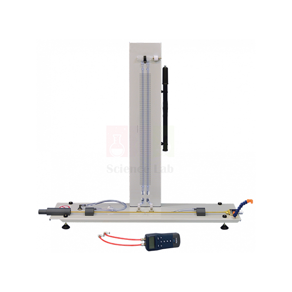
Friction Loss In Pipe
The Friction Loss In Pipe apparatus (Product Code: SLE/EFM/09) measures the pressure lost as water flows along a test pipe, across both laminar and turbulent regimes. Static pressure tappings either side of the pipe feed a water manometer for small differentials and a hand-held digital pressure meter for larger ones, while a precision needle valve sets the flow. The apparatus stands on a hydraulic bench and is made by Jain Scientific Equipments Pvt Ltd (ScienceLab), Ambala, for fluid mechanics courses at engineering colleges and polytechnics.
Specifications
| Parameter | Detail |
|---|---|
| Pressure tappings | Static tappings upstream and downstream of the test pipe |
| Low-range measurement | Water manometer for lower differential pressures in the laminar and lower turbulent regions |
| High-range measurement | Hand-held digital pressure meter for higher pressures in the turbulent region |
| Manometer mounting | Back panel with calibrated scales |
| Manometer datum | Air valve and hand-pump for adjusting the datum |
| Flow control | Precision needle valve downstream of the test pipe |
| Water supply | Stands on a hydraulic bench; Header Tank supplies the test pipe for low flow rate experiments |
Typical Use
Students set the apparatus on the hydraulic bench and fit the Header Tank, which provides a steady supply for the low-flow runs. Starting with the needle valve nearly closed, they read the head loss on the water manometer, collect a timed volume to find the flow rate, then open the valve a little and repeat. At low flows the head loss rises in direct proportion to velocity; as the flow increases past transition the relationship steepens, and the class switches to the digital pressure meter to follow the higher differentials in the turbulent region.
Plotting friction factor against Reynolds number turns the readings into a small Moody-style chart and lets students compare their laminar results with the theoretical Poiseuille line. As mechanics lab equipment for India’s civil and mechanical engineering syllabi, the apparatus supports reports on pipe design, pump sizing and energy loss. Use the hand-pump to bring the manometer levels to a convenient datum before each series, and bleed air from the tappings so readings settle quickly.
Manufacturer
Jain Scientific Equipments Private Limited produces the Friction Loss In Pipe apparatus in Ambala, Haryana, marketing it under its ScienceLab trade name to colleges and training institutions. More about the company is on our company profile.
Related Fluid Mechanics Equipment
Other pipe-flow and energy-loss apparatus often used in the same course:
- Bernoulli’s Theorem — the energy equation that head loss modifies
- Pipe Flow And Nozzle Kit — further pipe and nozzle flow experiments
- Viscosity And Particle Drag — explores the viscosity that governs laminar friction
- Water Hammer Apparatus — shows pressure surges when pipe flow is stopped suddenly
Browse the Fluid Mechanics category for flumes, pumps and pressure apparatus.
Frequently Asked Questions
Which flow regimes can be studied?
Laminar and turbulent. The water manometer covers the laminar and lower turbulent regions; the hand-held digital pressure meter covers the higher pressures of the turbulent region.
Is a hydraulic bench included?
The apparatus is designed to stand on a hydraulic bench, which is not listed as part of this item. Please contact us to discuss a suitable water supply.
What is the Header Tank for?
It supplies the test pipe during low flow rate experiments, giving a steady head for laminar-region readings.
How is flow controlled?
By a precision needle valve downstream of the test pipe, which allows fine, accurate adjustment.
What are the test pipe diameter and length?
These dimensions are not given on this page; we can confirm them with your quotation.
Can a calibration certificate be provided for the pressure meter?
Raise any certificate requirement with our team at the enquiry stage and we will advise.
Do you ship to colleges abroad?
Yes. We supply institutions in India and international markets.
Request a Quote
For a quotation on the Friction Loss In Pipe apparatus, write to us with your quantity and location, or add it to the enquiry cart.
Last updated: 24 September 2026
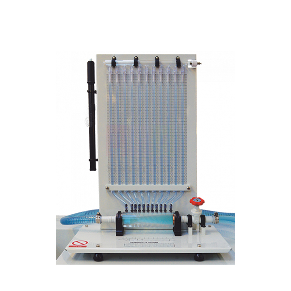
Bernoulli's Theorem
The Bernoulli’s Theorem apparatus (Product Code: SLE/EFM/10) demonstrates the exchange between pressure and velocity as water passes through a horizontal Venturi tube. Manometer tubes held vertically on a scaled panel show the pressure head at points along the tube, so students can see pressure fall in the throat and recover downstream. Built with plastic materials and corrosion-resistant finishes, it is manufactured by Jain Scientific Equipments Pvt Ltd (ScienceLab), Ambala, as lab equipment for college and polytechnic fluid mechanics practicals.
Specifications
| Parameter | Detail |
|---|---|
| Main components | Horizontal Venturi tube, downstream flow-control valve and manometer tubes |
| Manometer panel | Holds the tubes vertically, with a scale behind them for direct reading of water levels |
| Manifold | Common manifold above the tubes with an air pressure-control valve |
| Datum adjustment | Hand-pump connected to the air valve above the manometer tubes |
| Flow control | Downstream valve, so it causes no upstream turbulence |
| Base | Adjustable feet |
| Materials | Plastic materials and corrosion-resistant finishes throughout |
Typical Use
After levelling the base on its adjustable feet, students open the flow-control valve to set a steady flow and read the water level in each manometer tube against the panel scale. The heads drop towards the narrow throat of the Venturi, where velocity is highest, and rise again as the section widens. Using the measured flow and the tube cross-sections, the class calculates velocity head at each station and checks whether the total head stays constant, as Bernoulli’s equation predicts, or falls slightly because of friction.
Placing the control valve downstream keeps the approach flow undisturbed, so the readings reflect the Venturi itself rather than turbulence from a partly closed valve. If the water levels sit too high or too low on the scale, a hand-pump on the manifold air valve brings them back to a convenient datum. For engineering educational equipment in India, this apparatus also introduces the Venturi meter as a practical flow-measuring device, a topic students revisit in pump and pipe-network work. Drain the tubes after use and keep the panel scale clean.
Manufacturer
This apparatus is manufactured in Ambala, Haryana, by Jain Scientific Equipments Private Limited, whose ScienceLab brand covers fluid mechanics, physics and wider laboratory teaching equipment. Our company profile tells you more about who we are.
Related Fluid Mechanics Equipment
Apparatus that follows on naturally from the Bernoulli experiment:
- Cavitation In Venturi — what happens when throat pressure drops too far
- Friction Loss In Pipe — quantifies the head losses that Bernoulli’s ideal equation ignores
- Pipe Flow And Nozzle Kit — more pressure-velocity experiments in pipes and nozzles
- Two Stage (Series And parallel) — uses a Venturi meter for flow measurement in a pump rig
The complete Fluid Mechanics range lists further hydraulics apparatus.
Frequently Asked Questions
What does the Bernoulli’s Theorem apparatus include?
A horizontal Venturi tube, a downstream flow-control valve and manometer tubes on a panel, with a common manifold and air pressure-control valve, on a base with adjustable feet.
Why is the flow-control valve downstream?
So it does not cause any turbulence upstream of the Venturi, keeping the readings clean.
How is the manometer datum adjusted?
Students connect a hand-pump to the air valve above the manometer tubes. Whether a hand-pump is supplied with the unit can be confirmed through our contact page.
What water supply does it need?
Supply requirements are not listed on this page; our team can advise on connecting it in your lab.
Will it corrode with regular use?
It uses plastic materials and corrosion-resistant finishes throughout to protect against corrosion.
How many manometer tubes and what Venturi dimensions?
These details are not published here; please ask us and we will send them with the quotation.
Can we order several sets for a class?
Yes. Send the quantity and delivery location; we supply institutions in India and international markets.
Request a Quote
Request pricing for the Bernoulli’s Theorem apparatus via our contact form, or add it to the enquiry cart together with the other fluid mechanics equipment on your list.
Last updated: 24 September 2026
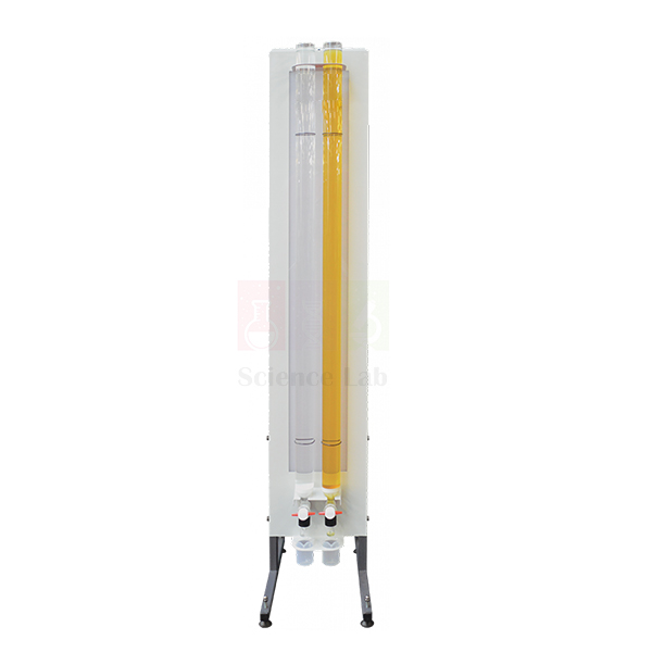
Viscosity And Particle Drag
Viscosity And Particle Drag (Product Code: SLE/EFM/11) is a simple falling-sphere viscometer that shows students how the viscosity of a liquid resists a sphere dropping through it. The self-standing unit holds two glass tubes of test fluid side by side, so two liquids can be compared in one session without repeated draining and refilling. It is used in fluid mechanics teaching laboratories of engineering colleges, polytechnics and technical institutes, and is made by Jain Scientific Equipments Pvt Ltd (ScienceLab), Ambala, as part of its engineering lab equipment in India.
Specifications
| Parameter | Detail |
|---|---|
| Type | Falling-sphere viscometer, self-standing unit |
| Test columns | Two glass tubes, each filled with a chosen test fluid for direct comparison |
| Illumination | Back plate with a low-voltage backlight so the spheres stay visible through the fluid |
| Draining | Valve system at the tube base that minimises fluid loss and helps empty the tube after tests |
| Test bodies | Spheres chosen for the correct density and size for each fluid; shapes must fit through the valve at the base |
| Suitable test fluids | Water, thin machine oil, castor oil and motor oil |
| Measurement method | Stopwatch timing of the sphere as it falls a set distance down the tube |
Typical Use
Students fill the two tubes with the liquids they want to study, pick a sphere whose density and size suit each fluid, and release it at the top of the column. Once the sphere has settled to a steady speed, they time it over the marked fall distance with a stopwatch. From the fall time they work out the terminal velocity and relate it to the drag on the sphere and the viscosity of the liquid — the classic Stokes’ law exercise. Running water in one tube and castor oil in the other makes the contrast between a thin and a thick fluid obvious to the whole group.
For consistent readings, let air bubbles clear before each drop, release the sphere along the centre of the tube, and repeat several drops per fluid to average the times. Because viscosity changes with temperature, note the room temperature with each data set. Departments looking for a viscosity measurement apparatus in India that also introduces particle drag will find the twin-tube layout saves bench time between groups.
Manufacturer
This twin-tube viscometer comes from Jain Scientific Equipments Private Limited, a company based in Ambala, Haryana, that sells its laboratory products under the ScienceLab name. Its fluid mechanics line is designed around practical teaching in engineering and applied science courses. Learn more about the business on our company profile.
Related Laboratory Equipment
Items a lab usually sets out alongside a falling-sphere viscosity practical:
- Stopwatch, Digital — times the sphere over the set fall distance
- Steel Ball — extra spheres for drop tests; check the size passes the base valve
- Glass Measuring Cylinder — handy for measuring and transferring test fluids
- Lift And Drag — takes drag studies further with force measurement on models in a flume
See the complete Fluid Mechanics range for more teaching apparatus.
Frequently Asked Questions
Can two liquids be tested in the same session?
Yes. The unit holds two glass tubes, so a different fluid can stay in each one for side-by-side comparison without draining between groups.
Which test fluids are suitable?
Water, thin machine oil, castor oil and motor oil are listed as suitable. For any other liquid, contact us before use.
Are the test spheres included, and in what sizes?
The apparatus is used with spheres selected for the right density and size for each fluid, and every shape must fit through the base valve. Please confirm the exact set of spheres supplied when you request a quotation.
Is a stopwatch supplied with the unit?
Timing is done with a stopwatch, but one is not listed as part of the unit. A digital stopwatch can be added to your order.
How is the unit emptied and cleaned after oil tests?
The valve system at the base drains the tube with minimal loss. Collect used oil in a suitable container and wipe spheres clean before storing them.
Is a calibration certificate available?
This is a teaching viscometer rather than a reference instrument; discuss any certificate needs with us through the contact page.
Can you supply several units for a college or export order?
Yes. Send the quantity, delivery location in India or abroad, and any special needs, and we will reply with pricing and lead time.
Request a Quote
For prices and availability, contact us or add this apparatus to your enquiry cart. We supply institutions across India and international markets.
Last updated: 24 September 2026
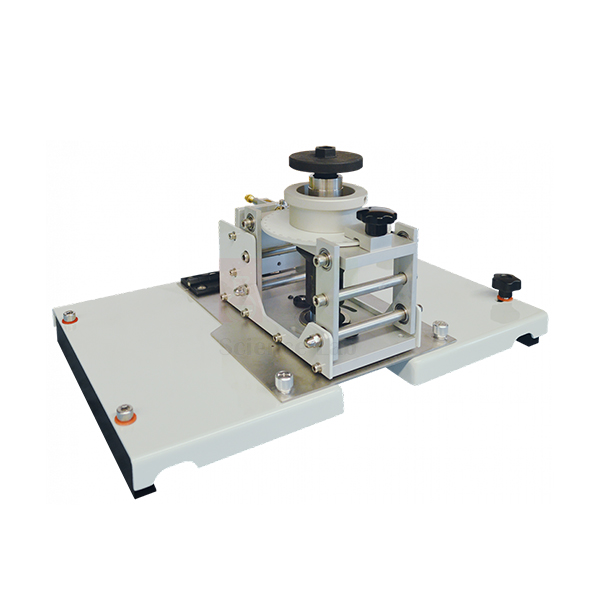
Lift And Drag
Lift And Drag (Product Code: SLE/EFM/12) is a force balance for measuring the hydrodynamic force on a model placed in the water flow of a laboratory flume. Its balance assembly is an articulated parallelogram linked to a load cell, and a separate display unit shows the measured force. The apparatus is aimed at civil and mechanical engineering departments teaching how bodies in a moving fluid experience lift and drag, and it is built by Jain Scientific Equipments Pvt Ltd (ScienceLab), Ambala, a maker of lab equipment for technical institutes.
Specifications
| Parameter | Detail |
|---|---|
| Balance type | Articulated parallelogram linked to a load cell |
| Force path | Parallelogram resists bending moments so only the force on the model reaches the load cell |
| Mounting | Balance assembly sits on a carrier that runs along the rails of the flume |
| Readout | Display unit showing the force measured by the load cell |
| Display mounting | Display unit hangs on the flume |
| Used with | A laboratory flume with rails (flume not listed as part of this item) |
Typical Use
A test model is attached to the balance and lowered into the flow, and the carrier is rolled along the flume rails to place it in the working section. As water passes the model, the parallelogram linkage keeps the model’s orientation steady and passes only the fluid force to the load cell, so turning moments do not distort the reading shown on the display unit. Students change the flow rate or the model’s shape and orientation, record the force each time, and plot how it varies — the basis for discussing drag coefficients, streamlining and lift on inclined bodies.
Zero the display with the model in still water before each series, allow the flow to stabilise after every change, and keep the carrier rails clean so the assembly runs freely. As engineering lab equipment in India, the balance suits both undergraduate practicals and simple project work on bluff and streamlined shapes.
Manufacturer
ScienceLab is the brand under which Jain Scientific Equipments Private Limited of Ambala, Haryana, designs and supplies hydraulics teaching equipment such as this balance. The company is a registered MSME manufacturer (Udyam UDYAM-HR-01-0003714), and its overseas consignments move under DGFT Importer-Exporter Code AAECJ8618A. Background on the company is on our company profile page.
Related Fluid Mechanics Equipment
Other items used in the same flume-based flow experiments:
- Meter Flume — an open-channel flume for the flow; confirm rail fit with us before ordering
- Bridge Piers — profiled piers for observing flow around bodies in the same channel
- Sluice Gate with Tappings — a further flume accessory for pressure and depth studies
- Viscosity And Particle Drag — introduces drag on falling spheres before force-balance work
Browse the full Fluid Mechanics category for flumes and accessories.
Frequently Asked Questions
Is the flume included with Lift And Drag?
No flume is listed as part of this item; the balance is built to run on a flume’s rails with the display unit hung on the flume. Tell us which flume you have so we can check the fit.
Why use a parallelogram linkage instead of a simple arm?
The parallelogram resists bending moments, so only the force acting on the model is transmitted to the load cell, giving a cleaner force reading.
Does it read lift and drag at the same time?
The balance passes the model force to one load cell shown on the display unit. For the exact measuring arrangement for lift and for drag, please contact us.
Which test models come with the balance?
Models are not specified in our current product details; ask us for the model shapes available with your order.
How should the load cell be looked after?
Avoid knocking or overloading the balance, dry the assembly after use and store it off the flume when the lab is idle.
What warranty applies?
Warranty terms are given with the quotation; contact us for current terms.
What should an institutional enquiry include?
Share the quantity, your flume details, delivery location and any tender documents required, and we will respond with a formal offer.
Request a Quote
To order Lift And Drag for your fluids lab, contact us or place it in the enquiry cart. Supply is available across India and international markets.
Last updated: 24 September 2026
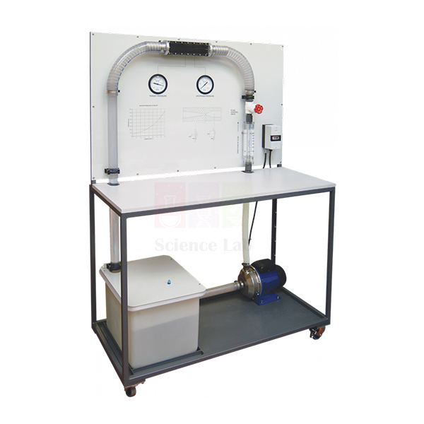
Cavitation In Venturi
Cavitation In Venturi (Product Code: SLE/EFM/13) is a self-contained, mobile teaching unit that produces clearly visible cavitation in a Venturi so students can watch vapour bubbles form and collapse while taking flow and pressure readings. It gives mechanical, chemical and civil engineering students hands-on practice with the continuity equation and Bernoulli’s equation in a setting where the theory visibly breaks down. The unit is produced by Jain Scientific Equipments Pvt Ltd (ScienceLab), Ambala, an engineering lab equipment manufacturer serving colleges and polytechnics.
Specifications
| Parameter | Detail |
|---|---|
| Construction | Robust frame holding all components; self-contained, mobile unit |
| Main components | Water tank, electric pump, flow-control valve, flow meter and Venturi |
| Pressure measurement | Pressure gauges upstream of the Venturi and at the Venturi throat |
| Temperature | Thermometer showing the temperature of the water in the tank |
| Safety features | Pump with electrical protection; water tank with splash cover to prevent spillage |
| Learning outcomes | Calculating flow and pressure, different methods of creating cavitation, and causes of error |
Typical Use
With the pump running, students open the flow-control valve step by step and read the flow meter together with the gauges upstream of the Venturi and at its throat. As velocity through the throat rises, throat pressure falls until it reaches the vapour pressure of the water and a cloud of bubbles appears. Comparing the measured pressure drop with the value predicted by the continuity and Bernoulli equations shows where simple theory holds and where losses and cavitation take over. Because vapour pressure depends on temperature, the tank thermometer reading is recorded with every set of results.
Classes can explore more than one way of bringing on cavitation and then discuss the sources of error in their calculations. Keep the splash cover in place while running, top up the tank with clean water, and let the pump stop before adjusting pipework. As lab equipment for college India departments, the unit wheels between rooms, so one set can serve several practical groups.
Manufacturer
Cavitation In Venturi is part of the hydraulics range made by Jain Scientific Equipments Private Limited, a private limited company in Ambala, Haryana, whose products carry the ScienceLab brand. For details of the company’s background and other product lines, visit our company profile.
Related Fluid Mechanics Equipment
Apparatus that fits the same run of pressure and flow practicals:
- Bernoulli’s Theorem — establishes the Venturi pressure–velocity theory before cavitation is introduced
- Calibration of a Pressure Gauge — shows students how the dial gauges they read actually work
- Pressure Measurement Bench — broader practice with pressure measuring methods
- Water Hammer Apparatus — a companion study of pressure effects in pipe flow
More hydraulics teaching units are listed in our Fluid Mechanics category.
Frequently Asked Questions
Does the unit need an external water supply or hydraulic bench?
No. It carries its own water tank, electric pump, flow-control valve and flow meter on one frame, so it works as a self-contained unit.
Where is pressure measured?
Pressure gauges read the pressure upstream of the Venturi and at the Venturi throat.
Why is there a thermometer on the tank?
Water temperature affects its vapour pressure and therefore when cavitation starts, so the thermometer lets students record it with each result.
Is it safe to run in a classroom?
The pump includes electrical protection and the tank has a splash cover to prevent spillage. Normal lab supervision still applies.
What electrical supply does the pump need?
Supply voltage is not given in our current product details; contact us with your local mains supply so we can confirm.
Can a calibration certificate be provided for the gauges?
Please discuss certificate requirements with us at the time of enquiry through our contact page.
Do you supply universities outside India?
Yes, we handle orders for institutions in India and international markets; include the destination in your enquiry.
Request a Quote
For a quotation on Cavitation In Venturi, contact us or add it to the enquiry cart with any other equipment for your lab.
Last updated: 24 September 2026
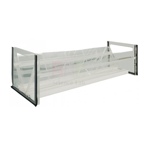
Trapezoidal Flume
Trapezoidal Flume (Product Code: SLE/EFM/14) is a clear acrylic flow-measuring flume with a 60° trapezoidal profile, intended for measuring discharge in an open channel with particular emphasis on low-flow situations. Because the body is transparent, students can watch the water surface change as it passes through the section rather than simply reading a number. It suits hydraulics and irrigation engineering teaching, and is manufactured by Jain Scientific Equipments Pvt Ltd (ScienceLab), Ambala, whose engineering educational equipment is used in colleges across India.
Specifications
| Parameter | Detail |
|---|---|
| Type | Trapezoidal flow-measuring flume |
| Material | Clear acrylic |
| Profile | 60° trapezoidal section |
| Purpose | Measurement of flows, with emphasis on low-flow situations |
| Installation | Channel mounting details confirmed on enquiry |
Typical Use
Measuring flumes work by narrowing the channel so the flow passes through critical depth; once that happens, a single upstream depth reading can be related to discharge. A trapezoidal section keeps useful sensitivity when only a little water is flowing, which is why this flume is chosen for low-flow gauging exercises such as small streams, irrigation furrows and drainage outlets. In the lab, students set a series of flow rates, read the upstream water level for each, and build a depth–discharge rating curve that they compare with the flow measured independently.
Seal the flume carefully in its channel so no water bypasses the section, level it before taking readings, and allow the flow to settle after each change. Clean acrylic with water and a soft cloth only, as solvents can craze clear plastics. Beyond routine practicals, the flume also serves as lab equipment for research in India on small-channel flow measurement.
Manufacturer
The flume is produced in Ambala, Haryana, by Jain Scientific Equipments Private Limited. ScienceLab is the company’s trading name for its educational and laboratory equipment, including open-channel hydraulics apparatus. Our company profile has more about who we are.
Related Fluid Mechanics Equipment
Open-channel items commonly used in the same hydraulics practical sequence:
- Meter Flume — a laboratory channel with recirculating supply; ask us to confirm fitting
- Culvert — clear culvert models for open and orifice flow studies
- Sluice Gate with Tappings — control-structure experiments with pressure readings
- Self Regulating Siphon — another clear acrylic model for discharge control studies
View all items in the Fluid Mechanics category.
Frequently Asked Questions
What is this flume best suited to measure?
Flow rates in open channels, with the emphasis on low-flow situations where many other measuring structures lose sensitivity.
Why is it made of clear acrylic?
Transparency lets students see the water surface profile and the change in depth through the flume while they take readings.
Does it come with a channel or water supply?
It is a flume section only; no channel or pump is listed with it. Share your channel details via our contact page so we can advise on fitting.
What overall dimensions does it have?
Dimensions beyond the 60° trapezoidal profile are not listed in our current product details; contact us for a drawing.
How do I keep the acrylic clear?
Rinse with clean water after use, wipe with a soft cloth and avoid solvents or abrasive pads.
What warranty is offered?
Warranty terms are stated in our quotation; ask us for current terms.
Request a Quote
Ready to add low-flow measurement to your hydraulics lab? Contact us or add the Trapezoidal Flume to your enquiry cart; we supply India and international markets.
Last updated: 24 September 2026
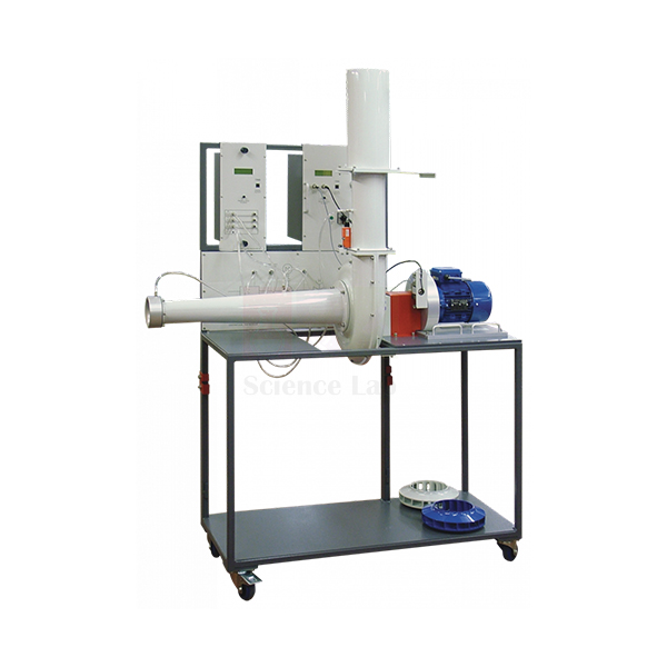
Centrifugal Fan Module
Centrifugal Fan Module (Product Code: SLE/EFM/15) is a trolley-mounted test rig for measuring how a centrifugal fan performs as its speed and airflow change. The module carries the fan and its instrumentation on a robust, mobile trolley, and it comes with three different impellers so students can compare blade designs on the same housing. It is designed for mechanical engineering turbomachinery and air-handling practicals, and is made by Jain Scientific Equipments Pvt Ltd (ScienceLab), Ambala, a technical educational equipment manufacturer.
Specifications
| Parameter | Detail |
|---|---|
| Layout | Fan and instrumentation mounted on a robust, mobile trolley |
| Impellers | Interchangeable; three different impellers supplied with the fan |
| Speed | Fully variable up to the maximum allowable for the fan |
| Speed, torque and power | Measured by the Universal Dynamometer |
| Airflow measurement | Shaped inlet nozzle used to measure the airflow rate |
| Airflow control | Slide-valve; air discharges past the valve to atmosphere |
| Safety | Housing interlock — the motor cannot run unless the fan is assembled correctly |
Typical Use
A standard practical holds the fan at a fixed speed and closes the slide-valve in stages, recording the pressure difference across the shaped inlet nozzle (which gives the airflow rate) together with the speed, torque and absorbed power from the Universal Dynamometer. From these readings students plot pressure rise, power and efficiency against flow, producing the fan characteristic curves covered in fluid machinery courses. Repeating the test at other speeds lets them check the fan laws, and swapping to each of the three impellers shows how blade shape changes the curves.
The interlocked housing means an impeller change can be done safely: switch off, open the housing, fit the next impeller and close it again before the motor will restart. Keep the inlet nozzle free of dust and obstructions, since its reading sets the flow for every result. Wheeling the trolley between labs makes one module practical for several batches of students.
Manufacturer
Engineering teaching rigs such as this fan module are built by Jain Scientific Equipments Private Limited, which operates as ScienceLab from Ambala in Haryana, India. You can read about our history and capabilities on the company profile.
Related Fluid Mechanics Equipment
Equipment that works with, or alongside, the fan module in a turbomachinery lab:
- Universal Dynamometer — measures the speed, torque and power absorbed by the fan
- Pipe Flow And Nozzle Kit — pipes that connect to a fan inlet for suction-flow tests; ask us to confirm pairing
- Axial Flow Pump Module — compares a different rotodynamic machine in the same course
- Reciprocating Compressor — contrasts a positive-displacement air machine with the fan
For pumps, turbines and more, open the Fluid Mechanics category.
Frequently Asked Questions
How many impellers are supplied?
Three different impellers are supplied with the fan, and they are interchangeable in the same housing.
Is the Universal Dynamometer part of this module?
The dynamometer provides the speed, torque and power readings and is also listed as a separate product. Please confirm in your enquiry whether you need it supplied with the module.
How is airflow measured and controlled?
Air enters through a shaped nozzle used to measure the airflow rate, and a slide-valve downstream sets how much air flows before it leaves to atmosphere.
Can students change the impeller safely?
Yes. An interlock on the fan housing stops the motor from running unless the fan is correctly assembled.
What is the maximum fan speed and power supply?
Speed is fully variable up to the fan’s maximum allowable value; the figures and mains requirement are not in our current listing, so please contact us.
Is a calibration certificate available for the instrumentation?
Talk to us about certificate needs when you request a quote; availability depends on the order.
What does an institutional quotation require?
Tell us the quantity, whether the dynamometer is needed, your delivery address and any tender format, and we will prepare the offer.
Request a Quote
For pricing on the Centrifugal Fan Module, get in touch or add it to our enquiry cart. We deliver to institutions in India and international markets.
Last updated: 24 September 2026
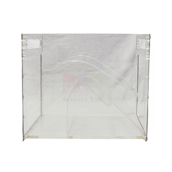
Self Regulating Siphon
Self Regulating Siphon (Product Code: SLE/EFM/16) is a clear acrylic hydraulic model that shows a siphon adjusting its own discharge over a wide range while holding the upstream water level almost constant. Unlike a simple siphon that runs either full or not at all, this one passes a mixture of air and water, which is the key to its self-regulating behaviour. The model helps civil and water-resources engineering students understand siphon spillways used for level control, and it is made by Jain Scientific Equipments Pvt Ltd (ScienceLab), Ambala, as part of its vocational training and engineering lab equipment.
Key Details
| Parameter | Detail |
|---|---|
| Type | Self-regulating siphon model |
| Material | Clear acrylic |
| Function | Adjusts its discharge automatically over a wide range |
| Upstream level | Kept mostly constant as discharge changes |
| Flow through siphon | Mixture of air and water |
| Suitable for | Open-channel hydraulics teaching and demonstration |
Typical Use
In a demonstration, the inflow to the model is raised in steps while students watch the siphon barrel through the transparent walls. At modest flows the siphon draws in air along with the water; as inflow increases, less air enters and more water passes, so the discharge rises while the upstream level barely moves. Recording the upstream level against discharge produces a remarkably flat curve, which students then compare with the steep level–discharge relationship of an ordinary weir or gate.
The model links neatly to real practice in canal and reservoir design, where siphon spillways protect structures from over-topping without moving parts. Fit it level and watertight in your channel, change flow slowly so each condition can settle, and rinse the acrylic with clean water after use. The mounting arrangement depends on your channel, so confirm fitting details with us before ordering.
Manufacturer
ScienceLab is the product brand of Jain Scientific Equipments Private Limited, an Ambala, Haryana company that builds hydraulics models for technical education. For tender and vendor registration, our details are GSTIN 06AAECJ8618A1ZT and LEI 3358004HRD1JIVXKYX49. The company profile page gives a fuller picture of the business.
Related Fluid Mechanics Equipment
Channel models used in the same series of open-channel experiments:
- Meter Flume — a recirculating laboratory flume to host channel models; confirm fitting with us
- Sluice Gate with Tappings — a gated control structure to contrast with siphon regulation
- Energy Dissipation — studies what happens to high-energy flow below spillway structures
- Culvert — another clear model showing how flow type changes with water level
Explore the wider Fluid Mechanics range.
Frequently Asked Questions
What makes this siphon “self-regulating”?
It passes a mixture of air and water, so its discharge adjusts automatically over a wide range while the upstream water level stays mostly constant.
Can students see what happens inside?
Yes. The model is clear acrylic, so the air–water mixture in the siphon is visible throughout the test.
Does it include a water supply or channel?
No supply or channel is listed with the model. Send us details of your flume or channel through the contact page and we will advise on fitting.
What size is the model?
Dimensions are not given in our current product details; ask us for a drawing before ordering.
How should the acrylic be cleaned?
Use clean water and a soft cloth; avoid solvents and abrasive cleaners, which can scratch or craze the surface.
Can you supply it for tenders or overseas orders?
Yes. We quote for institutional tenders and ship to India and international markets; include your quantity and destination.
Request a Quote
To price the Self Regulating Siphon, contact us or add it to your enquiry cart along with any other channel models you need.
Last updated: 24 September 2026
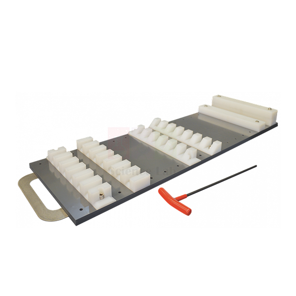
Energy Dissipation
Energy Dissipation (Product Code: SLE/EFM/17) is an open-channel accessory for studying how the energy of fast-moving water is dissipated below a hydraulic structure. It consists of a long apron and a selection of toothed and solid blocks that can be arranged in any combination on the apron, and it is designed to be used with the Spillway with Tappings. Civil and irrigation engineering departments use it to teach stilling-basin design, and it is manufactured by Jain Scientific Equipments Pvt Ltd (ScienceLab), Ambala, a TVET and engineering lab equipment manufacturer in India.
Key Details
| Parameter | Detail |
|---|---|
| Main component | Long apron |
| Blocks | Selection of toothed and solid blocks |
| Arrangement | Blocks can be placed in any combination on the apron |
| Used with | Spillway with Tappings (not part of this item) |
| Purpose | Study of the dissipation of energy |
Typical Use
Water leaving a spillway is fast and shallow, carrying enough energy to scour a riverbed if it is not tamed. With the apron placed downstream of the spillway, students first observe the flow and the hydraulic jump on the plain apron, then add toothed and solid blocks in different layouts and watch how the jump shortens, stabilises or moves. Measuring the water depths before and after the jump lets them calculate the energy lost for each arrangement and judge which layout performs best as a stilling basin.
Because the blocks can be arranged freely, groups can be set design challenges — for example, reaching a stable jump within the shortest length of apron. Record every layout with a sketch or photograph so results can be compared later, and dry the blocks before storage. The set is equally suited to TVET lab equipment lists for water-engineering diplomas and to degree-level hydraulics courses.
Manufacturer
The apron and block set is manufactured by Jain Scientific Equipments Private Limited, which trades as ScienceLab and operates from Ambala, Haryana. More about our work with engineering institutions is on the company profile page.
Related Fluid Mechanics Equipment
Channel equipment that fits the same spillway and scour experiments:
- Meter Flume — a recirculating flume to run the spillway and apron in; confirm fitting with us
- Sluice Gate with Tappings — another way to create fast flow ahead of a hydraulic jump
- Bridge Piers — continues the topic with scour of the stream bed around piers
- Self Regulating Siphon — an alternative spillway type for level control studies
All our hydraulics apparatus is listed under Fluid Mechanics.
Frequently Asked Questions
Is the spillway included?
No. Energy Dissipation is designed to be used with the Spillway with Tappings, which is not part of this item. Contact us about supplying both.
What blocks come with the apron?
A selection of toothed and solid blocks. The exact number of each is not listed in our current details, so please confirm it with your quotation.
Can the blocks be placed anywhere?
Yes. They can be arranged in any combination on the apron, which lets students compare many stilling-basin layouts.
What channel width does the apron fit?
Fitting dimensions are not in our current listing; share your flume details via the contact page so we can check.
How should the set be stored?
Rinse and dry the apron and blocks after use and keep the blocks together in a tray so none go missing between sessions.
What is needed for a college or tender quotation?
Let us know the quantity, whether you also need the spillway, the delivery location and any tender paperwork required.
Request a Quote
For a price on the Energy Dissipation set, contact us or add it to the enquiry cart. We supply institutions throughout India and international markets.
Last updated: 24 September 2026
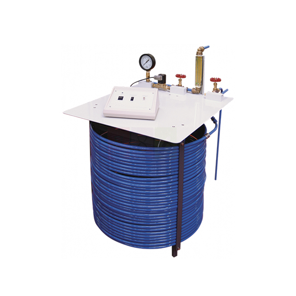
Water Hammer Apparatus
Water Hammer Apparatus (Product Code: SLE/EFM/18) lets students create and measure the pressure surge that travels along a pipe when flowing water is stopped suddenly. At its heart is a 60 m long coil of copper pipe with a solenoid valve at the discharge end; when the valve shuts, an electronic pressure transducer next to it captures the resulting pressure fluctuations. The apparatus serves mechanical and civil engineering courses on unsteady pipe flow, and it is made by Jain Scientific Equipments Pvt Ltd (ScienceLab), Ambala, among its engineering educational equipment for Indian and overseas institutions.
Specifications
| Parameter | Detail |
|---|---|
| Test pipe | Coil of copper pipe, 60 m long |
| Water inlet | Connects to your water supply |
| Fast-closing valve | Solenoid valve at the discharge end of the pipe |
| Flow control | Second adjustable valve at the discharge, downstream of the solenoid valve |
| Bypass valve | At the inlet end, discharging to waste; regulates the mean pipe pressure before the solenoid valve shuts and allows calibration of the pressure transducer |
| Transient measurement | Electronic pressure transducer near the solenoid valve |
| System pressure | Bourdon pressure gauge between the solenoid valve and the downstream control valve |
Typical Use
Students first set a steady flow through the coil with the downstream control valve and adjust the bypass valve to fix the mean pressure, reading it on the Bourdon gauge. Closing the solenoid valve then stops the water almost instantly, and the transducer records a sharp pressure rise followed by a decaying series of oscillations as the wave reflects back and forth along the pipe. From the period of these oscillations and the known pipe length they estimate the pressure-wave speed and compare the peak surge with the value predicted by Joukowsky’s equation.
The long coiled pipe stretches the wave’s travel time so it can be resolved clearly on a recording instrument. Before each session, use the bypass valve and Bourdon gauge to check the transducer calibration, and bleed trapped air from the pipe, as air pockets soften the surge. The rig is a practical choice among engineering educational equipment in India for showing why pipelines need surge protection.
Manufacturer
Jain Scientific Equipments Private Limited builds this apparatus under its ScienceLab label at Ambala in Haryana, where it develops pipe-flow and pressure teaching rigs for colleges and polytechnics. Find out more on our company profile.
Related Fluid Mechanics Equipment
Apparatus that pairs well with water hammer studies:
- Hydraulic Ram Pump — puts the water hammer effect to work to lift water
- Calibration of a Pressure Gauge — explains how the Bourdon gauge on this rig works
- Friction Loss In Pipe — covers steady pipe-flow losses before transients are introduced
- Cavitation In Venturi — another pressure effect students meet in pipe systems
See the rest of the Fluid Mechanics category.
Frequently Asked Questions
How long is the test pipe?
It is a coil of copper pipe 60 m long, which gives the pressure wave a measurable travel time.
Does it need a water supply?
Yes. The inlet connects to your water supply, and the bypass valve at the inlet end discharges to waste, so plan for a drain near the rig.
How are the pressure fluctuations recorded?
An electronic pressure transducer near the solenoid valve measures them. The display or recording instrument is not listed in our current details, so please contact us about readout options.
Can students check the transducer’s calibration?
Yes. The bypass valve sets the mean pipe pressure, which can be read on the Bourdon gauge and used to calibrate the transducer.
What electrical supply is needed for the solenoid valve and transducer?
Supply details are not in our current listing; tell us your mains supply through the contact page.
Is a calibration certificate supplied?
Any certificate requirement should be raised with us when you enquire, as availability depends on the order.
Do you ship outside India?
Yes, we supply institutions in India and international markets; include the destination and quantity in your enquiry.
Request a Quote
To receive a quotation for the Water Hammer Apparatus, contact us or add it to your enquiry cart.
Last updated: 24 September 2026
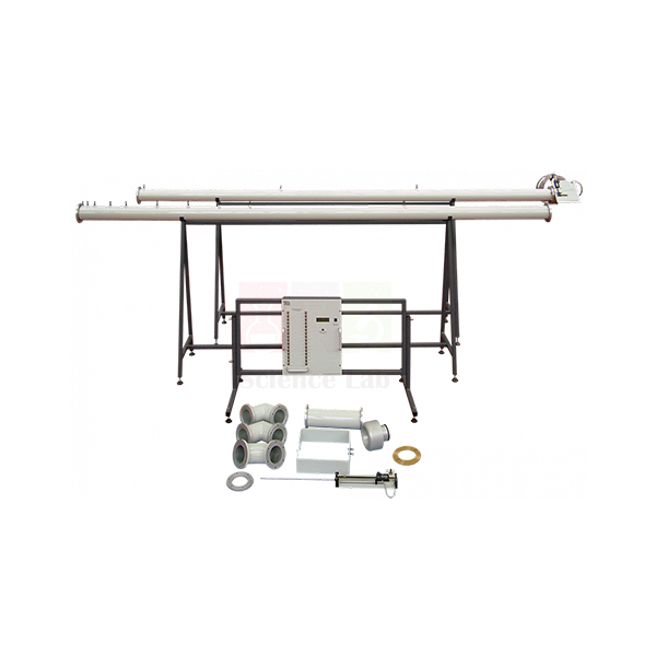
Pipe Flow And Nozzle Kit
Pipe Flow And Nozzle Kit (Product Code: SLE/EFM/19) is an air-flow accessory kit for studying pressure losses in pipes and fittings and for comparing different ways of measuring flow. The pipes connect to a fan inlet so the fan works in suction, drawing air through smooth-walled pipes fitted with many pressure tappings, a Pitot traverse, a nozzle and an orifice plate. It is intended for mechanical and aeronautical engineering practicals, and is manufactured by Jain Scientific Equipments Pvt Ltd (ScienceLab), Ambala, a supplier of lab equipment for college laboratories in India.
Specifications
| Parameter | Detail |
|---|---|
| Test pipes | Two long lengths of smooth-walled pipe with multiple pressure tappings |
| Connection | Pipes connect to the fan inlet, so the fan works in suction for pipe tests |
| Velocity profile | Pitot traverse fitted at the end of one long pipe |
| Nozzle study | Probe in an assembly that moves axially through an additional nozzle to measure its axial pressure profile |
| Flow comparison | Nozzle and orifice plate included for comparing measured flow |
| Fittings | Three: two elbows and a bend, each fitting between the long pipes |
| Pressure readout | Pipe tappings connect to a multiway pressure display |
Kit contents as described:
- Two long smooth-walled pipes with pressure tappings
- Pitot traverse
- Additional nozzle with axially moving probe assembly
- Orifice plate
- Two elbows and one bend
Typical Use
In the first exercise, students read static pressure at each tapping along a straight pipe and plot pressure against distance; the steady gradient gives the friction loss and, with the flow rate, the friction factor. Traversing the Pitot tube across the pipe end then gives the velocity profile, which they integrate to calculate the theoretical flow and compare with the readings from the nozzle and the orifice plate. Moving the probe step by step through the additional nozzle maps its axial pressure profile, showing how pressure converts to velocity as the flow accelerates.
Inserting the two elbows and the bend in turn between the long pipes isolates the extra pressure drop each fitting causes, so students can express it as a loss coefficient. Keep tapping tubes free of kinks, seal every joint well to avoid air leaks, and let the fan settle at each setting before reading.
Manufacturer
This kit is one of the air-flow teaching products developed by Jain Scientific Equipments Private Limited, known in the market as ScienceLab and located in Ambala, Haryana. Visit our company profile to learn about the organisation.
Related Laboratory Equipment
Items that support the same pipe-loss and flow-measurement work:
- Centrifugal Fan Module — a fan unit with a nozzle inlet; ask us to confirm it suits this kit
- Friction Loss In Pipe — the water-flow counterpart for pipe friction studies
- Bernoulli’s Theorem — underpins the nozzle and orifice flow calculations
- U Tube Manometer — for simple differential readings at individual tappings
More equipment is listed in our Fluid Mechanics category.
Frequently Asked Questions
What is included in the kit?
Two long smooth-walled pipes with pressure tappings, a Pitot traverse, an additional nozzle with an axially moving probe, an orifice plate, and three fittings — two elbows and a bend.
Does the kit include a fan?
No fan is listed in the kit; the pipes connect to a fan inlet. Tell us which fan you have, or ask about our Centrifugal Fan Module.
Is the multiway pressure display part of the kit?
The tappings are designed to connect to a multiway pressure display, but the display is not listed among the kit contents. Please contact us to add one.
What pipe diameter and length are used?
Exact dimensions are not in our current product details; ask us for the drawing.
How many flow-measurement methods can be compared?
Three: the Pitot traverse velocity profile, the nozzle and the orifice plate.
Is a calibration certificate available for the orifice plate or nozzle?
Discuss any certificate requirement with us at enquiry stage.
Can you quote for several kits or for export?
Yes. Include the quantity, fan details and delivery location in India or abroad.
Request a Quote
Ask for pricing on the Pipe Flow And Nozzle Kit through our contact page, or add it to the enquiry cart. We serve India and international markets.
Last updated: 24 September 2026
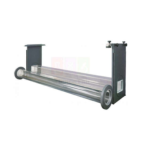
Culvert
Culvert (Product Code: SLE/EFM/20) is a pair of clear culvert models — one of circular section and one of rectangular section — for observing and calculating how water passes through a culvert under a road or embankment. The models let students see both open flow, where the water surface stays free inside the barrel, and orifice flow, where the inlet is submerged and the culvert runs under pressure. The pair is used in civil engineering hydraulics and highway drainage teaching, and is manufactured by Jain Scientific Equipments Pvt Ltd (ScienceLab), Ambala, a laboratory equipment exporter from India.
Key Details
| Parameter | Detail |
|---|---|
| Supplied as | A pair of culvert models |
| Sections | One circular, one rectangular |
| Construction | Clear, so the flow inside each barrel is visible |
| Flow regimes studied | Open flow and orifice flow in a culvert |
| Purpose | Observation and calculation of culvert flow |
Typical Use
One model is set across the channel and the flow is increased gradually. At low flows the inlet is not submerged and the barrel carries a free-surface stream; as the upstream (headwater) level rises and covers the inlet, the culvert switches to orifice-type flow. Students record headwater depth against discharge through both regimes, identify the transition, and compare the measured values with open-channel and orifice equations. Repeating the test with the other model shows how a circular barrel and a rectangular box culvert differ in capacity and in how they fill.
Because the models are clear, air pockets, entrance contraction and the point where the barrel runs full can all be seen directly. Seal the model edges so water cannot slip past, set the channel level, and wait for the headwater to stabilise before each reading.
Manufacturer
Jain Scientific Equipments Private Limited, incorporated under CIN U29309HR2020PTC087597, makes these models under the ScienceLab name in Ambala, Haryana. Its production runs at the licensed factory in HSIIDC Industrial Area, Saha, Ambala (Factory Licence AMB-ONLINE-CHD-J-414). Read more on our company profile.
Related Fluid Mechanics Equipment
Other items used in the same channel and hydraulic-structure practicals:
- Meter Flume — a recirculating channel to test the models in; confirm fitting with us
- Bridge Piers — the other common road-crossing structure studied in flumes
- Sluice Gate with Tappings — compares orifice-type flow under a gate
- Trapezoidal Flume — measures the discharge passing through the culvert
Find more hydraulic models in the Fluid Mechanics category.
Frequently Asked Questions
How many models are in the set?
Two: one culvert of circular section and one of rectangular section.
What is the difference between open and orifice flow here?
In open flow the inlet is not submerged and the water has a free surface inside the barrel; in orifice flow the inlet is covered and the culvert behaves like an orifice under head.
Is a flume needed?
Yes, the models are used in a water channel, and no channel is listed with them. Send your flume details through the contact page so we can advise on fit.
What are the model dimensions?
They are not stated in our current listing; contact us for sizes.
How do I clean clear models?
Rinse with clean water and wipe with a soft cloth; keep solvents away from the clear surfaces.
What warranty is provided?
Warranty terms are confirmed in the quotation; ask us for details.
Request a Quote
To order the Culvert model pair, contact us or use the enquiry cart. Orders are accepted from India and international markets.
Last updated: 24 September 2026
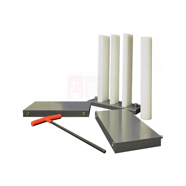
Bridge Piers
Bridge Piers (Product Code: SLE/EFM/21) is a set of four differently profiled bridge piers with a pair of sediment walls, used to show what happens to a river flow as it squeezes past the supports of a bridge. With the piers in a channel, students can observe the increased flow velocity and the streamline curvature between the piers, and watch scouring of the stream bed develop around them. The set is used in civil engineering courses on river hydraulics and bridge design, and is built by Jain Scientific Equipments Pvt Ltd (ScienceLab), Ambala, which makes lab equipment for technical institutes.
Key Details
| Parameter | Detail |
|---|---|
| Piers | Four bridge piers, each with a different profile |
| Sediment walls | One pair, to hold a sediment bed for scour studies |
| Observations | Increased flow velocity and streamline curvature between the piers |
| Bed effects | Scouring of the stream bed |
Typical Use
The sediment walls are placed across the channel to retain a layer of bed material, and one or more piers are set into it. When flow starts, the water speeds up through the narrowed openings between piers and the streamlines bend visibly around each nose. Over time a scour hole forms at the upstream face of each pier where the flow dives down and a horseshoe-shaped vortex lifts sediment. Students swap between the four profiles and compare how deep and how wide the scour becomes, and how strongly the water surface rises upstream.
Introducing a few drops of dye or small floating particles upstream makes the streamline curvature easy to photograph. Level the bed carefully before each run and keep the flow the same between profiles so comparisons are fair. The results connect directly to real decisions about pier shape and foundation depth on bridges over rivers.
Manufacturer
These pier models are made in Ambala, Haryana, by Jain Scientific Equipments Private Limited, the company behind the ScienceLab brand of educational and engineering apparatus. See our company profile for more information.
Related Fluid Mechanics Equipment
Useful companions for river and bridge hydraulics experiments:
- Meter Flume — a recirculating channel to run the piers in; confirm fitting with us
- Culvert — the other road-crossing structure taught alongside bridge piers
- Energy Dissipation — explores protecting a channel bed from high-energy flow
- Lift And Drag — measures the force the flow exerts on submerged bodies
Browse the full Fluid Mechanics range.
Frequently Asked Questions
What does the set include?
Four differently profiled bridge piers and a pair of sediment walls.
What are the sediment walls for?
They hold a bed of sediment in place so students can watch scouring of the stream bed around the piers.
Is sediment or a flume supplied?
Neither is listed with the set. Contact us with your flume details and we will advise on fitting and bed material.
Which pier profiles are included?
The set contains four different profiles; for the exact shapes and dimensions, please ask us.
How should the piers be cleaned after sediment tests?
Rinse off all sediment with clean water, dry the piers and walls, and store them flat to avoid warping.
Can you supply multiple sets for a department?
Yes. Send the quantity and delivery location in India or abroad, and we will quote with lead time.
Request a Quote
For a quotation on Bridge Piers, contact us or add the set to your enquiry cart. We supply India and international markets.
Last updated: 24 September 2026
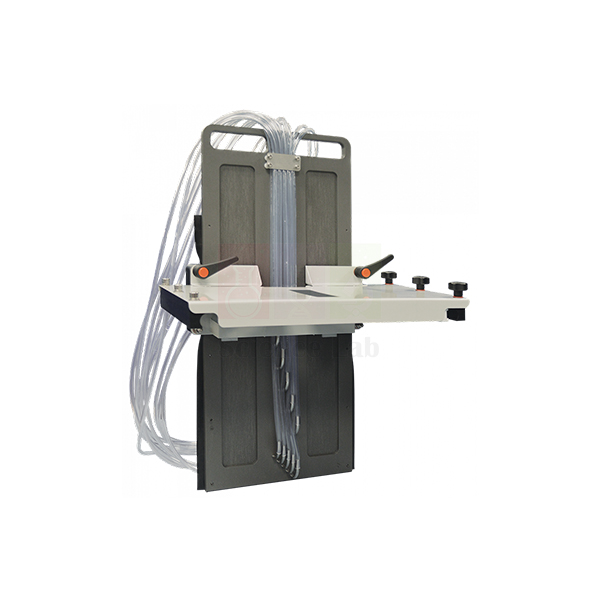
Sluice Gate with Tappings
Sluice Gate with Tappings (Product Code: SLE/EFM/22) is a flume accessory that lets students measure the water pressure acting on the face of a sluice gate. Ten pressure tappings run across the gate face, so the pressure distribution can be read directly and related to the flow rate and the upstream depth. It is intended for use with a flume (not included) in civil engineering and irrigation hydraulics labs, and is manufactured by Jain Scientific Equipments Pvt Ltd (ScienceLab), Ambala, a scientific laboratory equipment manufacturer.
Specifications
| Parameter | Detail |
|---|---|
| Type | Sluice gate for flume experiments |
| Pressure tappings | Ten, across the face of the gate |
| Investigations | Pressure changes across the gate face; variation of pressure with flow rate and depth |
| Used with | A flume, not included |
Typical Use
The gate is installed across the flume with a set opening beneath it, and each tapping is connected to a manometer or pressure display. At a given discharge, students read the upstream depth and the pressure head at every tapping, then plot pressure against position down the gate face. Near the top of the water the readings follow the hydrostatic line, but closer to the gate lip the pressure drops below hydrostatic as the flow accelerates towards the opening — a result that simple textbook assumptions miss.
By changing the flow rate and gate opening, the class sees how the distribution and the total force on the gate change with depth, and can compare the measured force with a hydrostatic estimate. Flush the tapping lines to clear air bubbles before each run, since trapped air gives false readings, and allow the upstream level to settle after every adjustment.
Manufacturer
The gate is produced by Jain Scientific Equipments Private Limited, an Ambala, Haryana manufacturer operating under the trade name ScienceLab. Our company profile explains more about the company and its product lines.
Related Laboratory Equipment
Items used with the gate in the same open-channel practicals:
- Meter Flume — a recirculating flume to install the gate in; confirm fitting with us
- Manometer, Glass — for reading pressure heads at the tappings
- Energy Dissipation — studies the fast flow and jump downstream of control structures
- Trapezoidal Flume — measures the discharge passing under the gate
More channel accessories are in our Fluid Mechanics category.
Frequently Asked Questions
How many pressure tappings does the gate have?
Ten, arranged across the face of the gate.
Is a flume included?
No. The gate is for use with a flume, which is not included. Tell us about your flume via the contact page so we can check compatibility.
What instrument reads the tapping pressures?
A manometer bank or a pressure display is needed; none is listed with the gate, so include your requirement in the enquiry.
Can the gate opening be varied?
The adjustment arrangement is not described in our current details; contact us to confirm how the opening is set.
Is a calibration certificate available?
This is a teaching model; raise any certificate needs with us when enquiring.
What details should I give for a quotation?
Quantity, flume make and width if known, delivery location in India or overseas, and any tender reference.
Request a Quote
To price the Sluice Gate with Tappings, contact us or add it to the enquiry cart. We supply India and international markets.
Last updated: 24 September 2026
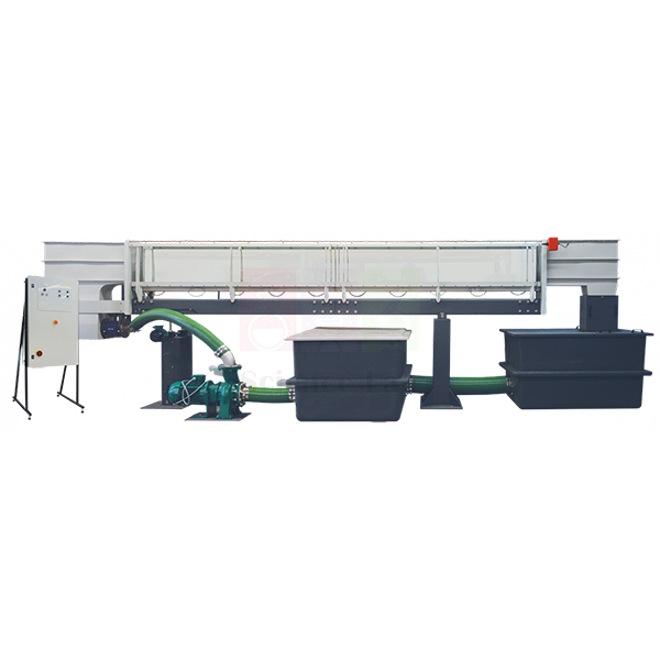
Meter Flume
Meter Flume (Product Code: SLE/EFM/23) is a 300 mm wide open-channel flume, available in lengths from 5 to 15 m, for student study and advanced research across a wide range of fluid flow topics. It has its own built-in recirculating water supply with a digital flow meter, and pressure tappings along the working section for detailed measurement. The flume forms the backbone of a university or institute hydraulics laboratory, and a large range of ancillaries is available to extend what it can teach. It is manufactured by Jain Scientific Equipments Pvt Ltd (ScienceLab), Ambala, a producer of engineering lab equipment in India.
Specifications
| Parameter | Detail |
|---|---|
| Channel width | 300 mm |
| Length | 5 to 15 m |
| Pressure tappings | At 0.25 metre intervals along the working section |
| Tapping connection | Multi-tube manometer or 32-way pressure display |
| Water supply | Built-in recirculating supply |
| Flow measurement | Digital flow meter connected to the recirculating supply |
| Ancillaries | Wide range available to extend the experiments |
| Application | Student study and advanced research into fluid flow topics |
Typical Use
A flume of this kind supports a full open-channel syllabus: uniform flow and Manning’s equation, specific energy and critical depth, hydraulic jumps, flow over weirs and under gates, and flow around structures such as culverts and bridge piers. Students set the discharge on the digital flow meter, install the structure being studied, and read water levels and the tapping pressures spaced every 0.25 metre along the working section to build surface and pressure profiles. Because the water recirculates, there is no need for a separate sump or mains supply during a session.
For research groups, the longer versions give more distance for flow to develop before it reaches a test model, and the 32-way pressure display option speeds up data collection. Keep the water clean to protect the flow meter, check that tapping lines are free of air before each run, and drain and dry the channel when it will stand unused. Choose the length that suits your room and experiments, and check ancillary fit with us when ordering.
Manufacturer
Larger laboratory installations like this flume are engineered by Jain Scientific Equipments Private Limited, which trades as ScienceLab from its base in Ambala, Haryana. Learn about the company on our company profile page.
Related Fluid Mechanics Equipment
Channel models and instruments used with a laboratory flume:
- Sluice Gate with Tappings — ten-tapping gate for pressure distribution studies
- Culvert — circular and rectangular culvert models for open and orifice flow
- Bridge Piers — profiled piers and sediment walls for velocity and scour tests
- Lift And Drag — rail-mounted force balance for models in the flow
- Trapezoidal Flume — clear flow-measuring section for low-flow work
The complete Fluid Mechanics category lists further apparatus.
Frequently Asked Questions
What lengths are available?
The flume is 300 mm wide and can be supplied from 5 to 15 m long. Tell us the space you have and we will suggest a length.
Does it need a separate pump or water supply?
No. It has a built-in recirculating water supply connected to a digital flow meter.
How are pressures along the channel measured?
Tappings at 0.25 metre intervals along the working section connect either to a multi-tube manometer or to a 32-way pressure display. Confirm which option you want in your enquiry.
Are the channel models included?
Ancillaries such as gates, culverts and piers are available separately, so the flume can be expanded over time.
What electrical supply and floor space are needed?
These depend on the chosen length and are not given in our current listing; contact us for installation details.
Can a calibration certificate be provided for the flow meter?
Please discuss certificate requirements with us when you request a quotation.
What warranty and installation support apply?
Terms are confirmed with the quotation; ask us for current details.
Do you supply flumes for overseas universities?
Yes, we quote for institutions across India and international markets; include the destination and required length.
Request a Quote
To plan a Meter Flume for your laboratory, contact us with the length you need, or add it to the enquiry cart.
Last updated: 24 September 2026
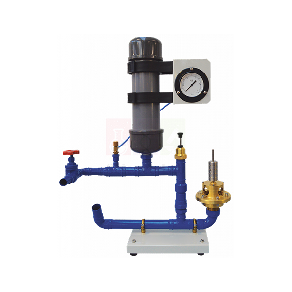
Hydraulic Ram Pump
Hydraulic Ram Pump (Product Code: SLE/EFM/24) demonstrates a pump with no motor at all: it uses the momentum of a large, slow-moving column of water to lift a smaller amount of water to a higher level. The apparatus has three main parts — a wall-mounted header tank, the pump, and the interconnecting pipework — with an inner and outer valve on the supply pipe and an air vessel to reduce hydraulic shock. It is used in mechanical, civil and agricultural engineering teaching, and is made by Jain Scientific Equipments Pvt Ltd (ScienceLab), Ambala, a laboratory instruments supplier in India.
Specifications
| Parameter | Detail |
|---|---|
| Pump type | Hydraulic ram — not a normal mechanically-operated pump |
| Main parts | Header tank, pump, and interconnecting pipework |
| Header tank | Mounts to a suitable wall |
| Valves | Supply pipe fitted with an inner and an outer valve |
| Outer valve loading | Weight platform for loading with the weights provided, which changes the pump’s cycle times |
| Shock control | Air vessel to reduce hydraulic shock |
| Weights | Provided |
Typical Use
Water runs down the supply pipe from the header tank and escapes through the outer valve until its speed is enough to snap that valve shut. The sudden stop acts like a plunger: the moving column’s energy forces some water through the inner valve into the delivery pipe, the air vessel cushions the pressure pulse, and the cycle repeats on its own. Students measure how much water is delivered and how much is spilled at the outer valve, then calculate the pump’s efficiency from the flows and heads involved.
Adding weights to the outer valve platform changes how long each cycle lasts, so the class can investigate how cycle time affects delivered flow and efficiency. Fix the header tank securely to a wall that can carry its full weight of water, keep the valves free of debris, and check the air vessel still holds air if the pump becomes noisy. The ram pump is a memorable way to show how the water hammer effect can be turned into useful work in places without electricity.
Manufacturer
Our hydraulic ram apparatus is manufactured by Jain Scientific Equipments Private Limited, better known by its ScienceLab brand, in Ambala, Haryana. Registered as an MSME manufacturing enterprise (Udyam UDYAM-HR-01-0003714), the company ships overseas orders under DGFT Importer-Exporter Code AAECJ8618A. Visit the company profile for more background.
Related Laboratory Equipment
Items that help with running and measuring a ram pump experiment:
- Water Hammer Apparatus — measures the pressure surge the ram pump relies on
- Stopwatch, Digital — times volume collection and valve cycles
- Measuring Cylinder 1000 ml — collects delivered and spilled water to find flow rates
- Vane Pump — a motor-driven pump for contrast with the ram principle
See more hydraulics apparatus in the Fluid Mechanics category.
Frequently Asked Questions
Does the ram pump need electricity?
No. It is not a normal mechanically-operated pump; it runs on the momentum of water flowing down from the header tank.
What is supplied?
The header tank, the pump with its inner and outer valves and air vessel, the interconnecting pipework, and the weights for the outer valve platform.
How is the header tank installed?
It mounts to a suitable wall, so plan a sturdy wall location near a water supply and drain.
What do the weights do?
Loading the outer valve platform with the weights provided changes the pump’s cycle times, letting students study their effect on performance.
What delivery height can it achieve?
Head and flow figures are not given in our current product details; contact us for performance data.
What warranty is offered?
Warranty terms are stated in the quotation; ask us for the current terms.
Can you supply several units for a department or an export order?
Yes. Share the quantity and delivery location, and we will send pricing and lead time.
Request a Quote
For a quotation on the Hydraulic Ram Pump, contact us or add it to your enquiry cart. We serve customers in India and international markets.
Last updated: 24 September 2026
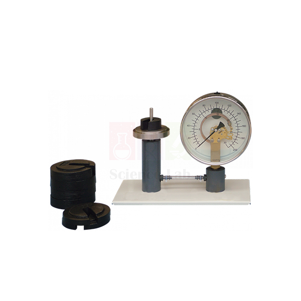
Calibration of a Pressure Gauge
Calibration of a Pressure Gauge (Product Code: SLE/EFM/25) is a teaching apparatus that shows both how a Bourdon-type pressure gauge works and how it is calibrated. A gauge with a transparent dial, so its working mechanism is on view, is connected to a dead weight tester; students load known weights, calculate the pressure they produce and compare it with the gauge reading. It introduces the principles of lab equipment calibration to mechanical, instrumentation and civil engineering students, and is manufactured by Jain Scientific Equipments Pvt Ltd (ScienceLab), Ambala.
Specifications
| Parameter | Detail |
|---|---|
| Arrangement | Pressure gauge connected to a dead weight tester |
| Gauge dial | Transparent, showing the working mechanism |
| Gauge mechanism | Thin-walled tube of oval cross-section bent into an arc; one end held rigidly and admitting pressure, the other free and linked to a dial and pointer |
| Pointer response | Moves by an amount proportional to the pressure increase as the tube tries to straighten |
| Dead weight tester | Weights on a platform apply a known force to a piston of known area |
| Pressure transfer | Flexible tube containing water carries the piston pressure to the gauge tube |
Typical Use
Students add weights to the dead weight tester platform in increments, and at each step they calculate the true pressure from the total load and the known piston area and write down the gauge reading. They then remove the weights step by step and record the readings again on the way down. Plotting gauge reading against true pressure for loading and unloading reveals the gauge’s error at each point and any hysteresis, and lets them draw up a correction chart.
Watching the oval tube through the clear dial as it tries to straighten under pressure makes the Bourdon principle easy to grasp, and many students meet this mechanics lab equipment before using dial gauges on larger rigs. Place the weights gently and centrally, rotate the piston slightly while readings are taken if the design allows, and make sure no air is trapped in the water-filled flexible tube.
Manufacturer
The apparatus is designed and built in Ambala, Haryana, by Jain Scientific Equipments Private Limited, which markets its instruments as ScienceLab. More details are on our company profile.
Related Laboratory Equipment
Pressure-measurement equipment that students use alongside this experiment:
- Bourdon Gauge — a stand-alone gauge of the same type for other pressure demonstrations
- Pressure Measurement Bench — compares different pressure-measuring methods
- Water Hammer Apparatus — applies a Bourdon gauge and a transducer in a working pipe rig
- Cavitation In Venturi — uses dial gauges to track pressure at a Venturi throat
Browse our Fluid Mechanics category for more.
Frequently Asked Questions
How is the pressure worked out during calibration?
The weights put a known force on a piston of known area, so pressure equals that force divided by the piston area.
Can students see inside the gauge?
Yes. The dial is transparent, so the oval tube, its fixed end and the pointer linkage are all visible.
What fluid is used in the system?
A flexible tube containing water transfers the pressure from the piston to the gauge tube.
What pressure range does the gauge cover?
The range and the weight set details are not listed in our current product information; contact us for these figures.
Does the apparatus come with a calibration certificate?
It is built to teach calibration rather than serve as a reference standard; talk to us about any certificate needs when you enquire.
How should it be maintained?
Keep the piston and cylinder clean, store the weights dry, and top up or bleed the water-filled tube if readings become erratic.
What should an institutional enquiry include?
Quantity, delivery location in India or abroad, and any tender format; we will reply with a formal quotation.
Request a Quote
For pricing on Calibration of a Pressure Gauge, contact us or add it to the enquiry cart. We supply India and international markets.
Last updated: 24 September 2026
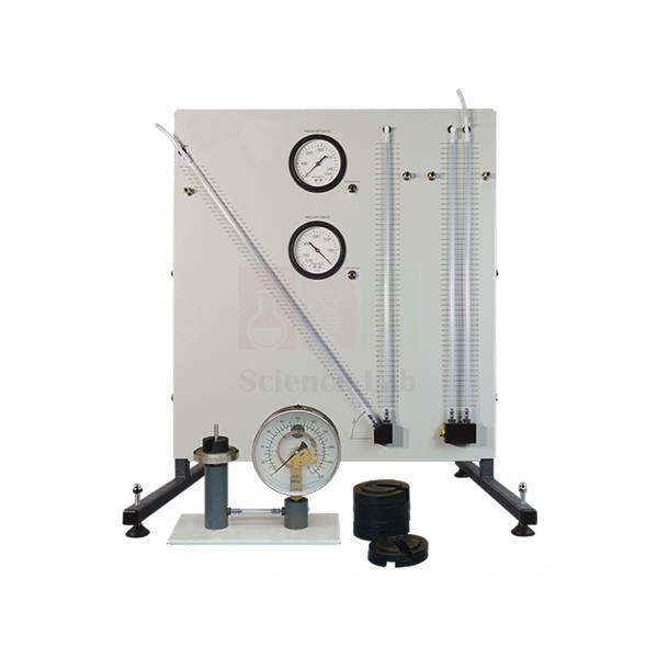
Pressure Measurement Bench
The Pressure Measurement Bench (Product Code: SLE/EFM/26) is a two-unit teaching apparatus that lets students investigate and compare vertical and inclined U-tube manometers with Bourdon-type vacuum and pressure gauges, and then see how a Bourdon gauge is calibrated. Because manometers and Bourdon gauges sit inside more complex instruments such as pneumatic comparators and flow indicators, the bench gives mechanical and instrumentation students a clear grounding in how these devices work before they meet them in larger systems. It is manufactured by Jain Scientific Equipments Pvt Ltd (ScienceLab), Ambala, as lab equipment for technical institutes, engineering colleges and polytechnics.
Key Details
| Parameter | Detail |
|---|---|
| Type | Bench apparatus for studying pressure-measuring instruments |
| Units supplied | Two: a manometers and gauges unit, and a Bourdon pressure gauge calibration unit |
| Manometers and gauges unit | Framed structure with a backboard carrying all the instruments listed below |
| Manometers | Vertical U-tube manometer; U-tube manometer with an inclined limb |
| Bourdon gauges | One gauge for measuring vacuum; one gauge for measuring positive pressure |
| Pressure source | Syringe assembly for pressurising and for reducing pressure |
| Calibration unit | Separate Bourdon gauge with dead-weight calibration apparatus, arranged so the Bourdon tube mechanism can be clearly observed |
| Learning focus | Operation, characteristics and principles of calibration of manometers and Bourdon gauges |
Typical Use
In a typical practical, students use the syringe assembly to apply a small positive pressure or a partial vacuum and read the vertical U-tube, the inclined-limb manometer and the matching Bourdon gauge side by side. Comparing the readings shows why an inclined limb spreads a small pressure change over a longer length of scale, why liquid-column instruments suit low pressures, and how a mechanical dial gauge responds to the same input. Changing the syringe setting slowly and letting the liquid columns settle before reading gives more consistent results.
The second half of the session moves to the calibration unit. Students load the dead-weight apparatus, note the Bourdon gauge reading against the known applied pressure, and build a calibration table or curve while watching the curved Bourdon tube move the pointer. The bench is well suited to fluid mechanics and instrumentation courses that need engineering lab equipment in India for both demonstration and small-group work.
Manufacturer
This bench is built by Jain Scientific Equipments Private Limited, a company based in Ambala, Haryana, that trades under the name ScienceLab and makes apparatus for engineering, science and technical teaching laboratories. Background on the company and its range is available in our company profile.
Related Fluid Mechanics Equipment
Apparatus that fits naturally into the same pressure-measurement or hydrostatics practical:
- Calibration of a Pressure Gauge — a dead-weight tester with a transparent-dial gauge for extra calibration practice
- Bourdon Gauge — a standalone gauge with a clear back for showing the tube mechanism at the front of a class
- U Tube Manometer — a borosilicate glass U-tube for separate pressure or differential-pressure demonstrations
- Manometer, Glass — a backplate-mounted glass manometer with stopcock for additional student stations
- Center of Pressure — the next hydrostatics topic: force and moment on a submerged plane surface
Explore the full Fluid Mechanics range for flow, pump and turbine apparatus.
Frequently Asked Questions
What is included with the Pressure Measurement Bench?
Two units: the manometers and gauges unit (vertical U-tube manometer, inclined-limb U-tube manometer, vacuum Bourdon gauge, pressure Bourdon gauge and syringe assembly on a framed backboard) and a separate Bourdon gauge calibration unit with dead-weight apparatus.
Why are there two different manometers?
So students can compare them directly. Tilting one limb makes the liquid travel further along the scale for the same pressure change, which makes small pressures easier to read than on a vertical U-tube.
Can the bench show vacuum as well as positive pressure?
Yes. One Bourdon gauge measures vacuum and the other positive pressure, and the syringe assembly can both raise and reduce the pressure applied to the instruments.
What pressure ranges do the gauges cover?
Gauge ranges and the manometer fill liquid are not stated in our current product description. Please contact us for the detailed datasheet before ordering.
Can a calibration certificate be supplied with the gauges?
This depends on the order; please discuss your requirement with us through the contact page at the enquiry stage.
What should we include in a request for an institutional quotation?
Tell us the number of benches, the delivery address or port, and any tender format you must follow. Warranty terms are stated in the quotation itself.
Do you supply multiple benches or ship abroad?
Yes. We supply colleges and training centres across India and international markets; quantities, packing and dispatch time are confirmed when we quote.
Request a Quote
For pricing on the Pressure Measurement Bench, send your requirement through our contact page or add the item to your enquiry cart.
Last updated: 24 September 2026
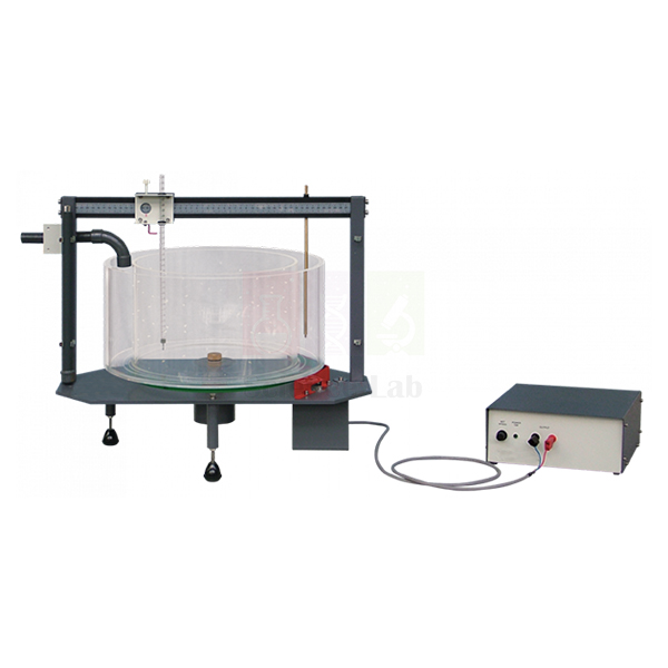
Vortex Apparatus
Vortex Apparatus (Product Code: SLE/EFM/27) is a rotating-vessel apparatus used to create a forced vortex in water and measure the shape of its free surface in engineering college and polytechnic fluid mechanics labs. A low-voltage, variable-speed motor spins the vessel about its vertical axis, and a traverse probe with a linear scale on each axis maps the surface point by point. It is manufactured by Jain Scientific Equipments Pvt Ltd (ScienceLab), an OEM manufacturer, at its own factory in Ambala, India.
Key Details
| Parameter | Detail |
|---|---|
| Type | Forced vortex apparatus with a rotating water vessel |
| Drive | Low-voltage, variable-speed motor rotating the vessel about its vertical axis |
| Speed control | Separate speed-control unit, sited away from the main apparatus |
| Water fill | Water added to the rotating vessel until it is about half full |
| Surface measurement | Traverse probe moving horizontally and vertically, with a linear scale on each axis |
| Total head measurement | Traverse probe can be replaced by a Pitot tube to measure the distribution of total head |
| Product code | SLE/EFM/27 |
| Manufacturer | Jain Scientific Equipments Pvt Ltd (ScienceLab) — OEM |
| Country of origin | India (made in Ambala, Haryana) |
What Is the Vortex Apparatus Used For?
Students start the vessel turning, add water until it is roughly half full and watch a forced vortex develop: the surface falls rapidly towards the centre and produces an air core. After a few minutes of steady rotation the vortex becomes constant, and only then are readings taken, stepping the traverse probe across the radius and recording surface height against radial position from the two scales. Repeating the traverse at different motor speeds shows how the profile deepens as rotation increases, and the results can be compared with the parabolic shape predicted by forced-vortex theory.
For a second set of readings the traverse probe is swapped for a Pitot tube, so the class can plot how total head varies across the vessel. Because the speed-control unit sits away from the vessel, the instructor can adjust rotation without disturbing the water, which suits group demonstrations as well as individual lab reports. It is practical engineering lab equipment in India for hydraulics and fluid mechanics syllabi at degree and diploma level.
OEM Manufacturer
ScienceLab is the trading name of Jain Scientific Equipments Private Limited, the OEM (original equipment manufacturer) of this vortex apparatus, which it builds at its own licensed factory at Saha, Ambala, Haryana, India. Engineering colleges, polytechnics, dealers and importers therefore deal with the maker itself rather than a trader: technical questions, replacement parts and repeat orders are handled at source, so just ask us. Learn more about the company on our company profile.
Related Fluid Mechanics Equipment
Other items that complement vortex experiments in the same hydraulics lab:
- Bernoulli's Theorem — builds on the total-head idea with a Venturi tube and manometer panel.
- Cavitation In Venturi — links pressure, velocity and flow in a visible demonstration.
- Pressure Measurement Bench — grounds students in manometer and gauge readings before head measurements.
- Stopwatch, Digital — times how long the vortex takes to settle before readings are taken.
The complete Fluid Mechanics category lists our pumps, flumes and flow apparatus.
Frequently Asked Questions
How is the speed of the Vortex Apparatus controlled?
The Vortex Apparatus uses a separate speed-control unit, sited away from the main apparatus, to drive its low-voltage, variable-speed motor. Keeping the controller apart lets the instructor change the rotation speed without disturbing the water surface being measured.
How do students measure the surface profile?
Students use the traverse probe of the Vortex Apparatus, which moves both horizontally and vertically. Each axis has a linear scale, so the height of the water surface can be recorded at known radial positions and plotted as a profile.
Can the Vortex Apparatus measure total head?
Yes. On the Vortex Apparatus the traverse probe can be replaced by a Pitot tube to measure the distribution of total head across the vessel. Please ask us to confirm whether a Pitot tube is included in your supply.
What are the vessel size and motor voltage?
The current Vortex Apparatus listing describes the motor only as low-voltage and variable-speed and does not state the vessel dimensions. Ask us through the contact page for the datasheet of the unit you are quoted before planning bench space.
How long before readings can be taken?
After water is added to the rotating vessel of the Vortex Apparatus, allow a few minutes of steady rotation. Once the forced vortex becomes constant and the surface stops changing shape, students can traverse the profile and record readings.
Who manufactures the Vortex Apparatus?
The Vortex Apparatus is manufactured by Jain Scientific Equipments Pvt Ltd (ScienceLab), the OEM, at its own licensed factory at Saha, Ambala, Haryana, India. Quotations, replacement-part enquiries and repeat orders are handled directly by the manufacturer.
Can you supply overseas institutions?
Yes. The Vortex Apparatus is supplied to colleges and training centres in India and international markets. Send the product code SLE/EFM/27, the quantity and the destination, and export packing and shipping are agreed at the quotation stage.
Request a Quote
To get a price for the Vortex Apparatus straight from its manufacturer, write to us via the contact form or place it in your enquiry cart with the quantity you need.
Last updated: 24 September 2026
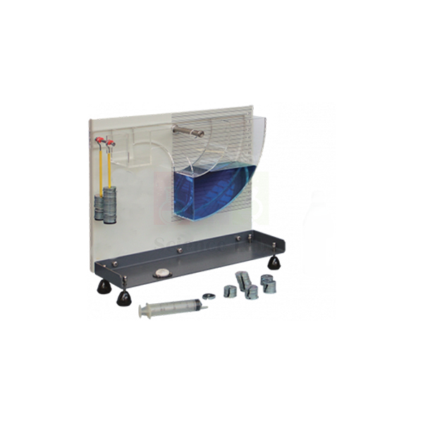
Center of Pressure
The Center of Pressure apparatus (Product Code: SLE/EFM/28) is a pivoted clear plastic assembly that students use to find the centre of pressure on a plane surface when it is totally or partially submerged in water. A clear quadrant mounted on a vertical panel holds the water, a scale shows the head, and weights hung from a lever arm balance the hydrostatic moment. Compact and self-contained, it is made by Jain Scientific Equipments Pvt Ltd (ScienceLab), Ambala, for hydrostatics practicals in engineering colleges, polytechnics and other buyers of mechanics lab equipment.
Key Details
| Parameter | Detail |
|---|---|
| Type | Pivoted centre of pressure (hydrostatic force) apparatus |
| Construction | Vertical panel holding a clear plastic quadrant, to which water is added |
| Head indication | Scale on the panel showing the head of water |
| Quadrant markings | Engraved lines to help set the plane surface vertical or at an angle |
| Quadrant geometry | Cylindrical sides with their central axis coincident with the moment measurement axis, so pressure on the curved faces exerts no moment about the pivot |
| Moment measurement | Weights suspended from a lever arm |
| Test conditions | Plane surface fully or partially submerged |
| Format | Compact, self-contained unit suited to classroom demonstrations |
Typical Use
The experiment works because of the quadrant's shape. Its curved sides are centred on the pivot, so the water pressure acting on them passes through the pivot and produces no turning effect; the only moment left is the one from pressure on the flat test face. Students add water in stages, read the head from the panel scale, and restore balance by adding weights to the lever arm. From the balancing moment they calculate the hydrostatic thrust and the depth of the centre of pressure, then compare it with the theoretical value for a partially submerged face and, once the water covers the face completely, for a fully submerged one.
Using the engraved lines, the plane can also be set at an angle to study inclined surfaces, a useful extension for civil and mechanical engineering groups. Level the panel before starting, add water gently to avoid splashing onto the balance side, and drain and dry the quadrant after the session to keep the clear plastic free of marks. The unit is a practical choice of lab equipment for college fluid mechanics courses that need a bench-top hydrostatics experiment.
Manufacturer
This apparatus comes from Jain Scientific Equipments Private Limited, an Ambala, Haryana manufacturer operating under the ScienceLab brand. For tender and vendor registration forms, the company's GSTIN is 06AAECJ8618A1ZT and its Legal Entity Identifier (LEI) is 3358004HRD1JIVXKYX49. More about the business is on our company profile.
Related Fluid Mechanics Equipment
Useful additions for a hydrostatics and pressure practical:
- Pressure Measurement Bench — manometers and Bourdon gauges for the pressure-measurement part of the same module
- Calibration of a Pressure Gauge — a dead-weight tester that relates known forces and areas to pressure
- Hangers with Slotted Weights — extra slotted weights if more balancing increments are needed (check fit with us)
- Measuring Cylinder, Polypropylene — an unbreakable cylinder for adding water to the quadrant in controlled steps
- Bernoulli's Theorem — the natural next step from fluid statics into flowing water
Browse our Fluid Mechanics equipment for further hydraulics apparatus.
Frequently Asked Questions
Why do the curved faces of the quadrant not affect the result?
Their central axis coincides with the moment measurement axis, so the fluid pressure on them produces no moment about the pivot. The measured moment comes only from pressure on the plane test surface.
Can inclined plane surfaces be tested?
Yes. Engraved lines on the quadrant help students hold the plane either vertical or at an angle.
Are the balance weights included?
The moment is measured with weights on a lever arm, but the weight set supplied is not detailed in our current description. Please contact us to confirm contents.
Does it need a water supply or hydraulic bench?
It is a self-contained unit; water is added directly to the quadrant, so a simple container or measuring cylinder is enough.
How should the clear plastic parts be cleaned?
Drain after use and wipe with a soft cloth and plain water; avoid abrasive pads or solvents, which can scratch or cloud clear plastics.
Is a calibration certificate or warranty provided?
Both are handled per order. Discuss certificate needs with us, and the warranty period will be stated in your quotation.
Can several units be ordered for a class?
Yes, multiple sets can be supplied for colleges and institutes across India and international markets; share the quantity when you enquire.
Request a Quote
Ask for a quotation on the Center of Pressure apparatus through our contact page, or collect several items in the enquiry cart and send them together.
Last updated: 24 September 2026
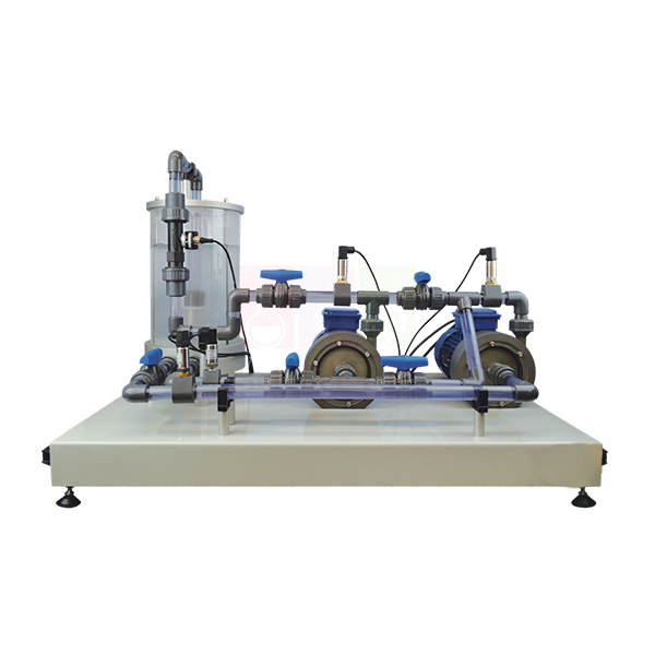
Variable Speed Series And Parallel Pumps
Variable Speed Series And Parallel Pumps (Product Code: SLE/EFM/29) is a bench-top test set for studying how centrifugal pumps perform on their own and when two are combined in series or in parallel. It pairs one variable speed and one fixed speed centrifugal pump, each driven independently by its own bearing-mounted motor, drawing from a clear acrylic reservoir. The set is built for fluid machinery and hydraulics laboratories in engineering and diploma institutions by Jain Scientific Equipments Pvt Ltd (ScienceLab), Ambala, a technical educational equipment manufacturer.
Key Details
| Parameter | Detail |
|---|---|
| Type | Bench-top centrifugal pump test set |
| Pumps | One variable speed centrifugal pump and one fixed speed centrifugal pump |
| Drive | Two bearing-mounted motors, each driving one pump independently |
| Operating modes | Single pump, two pumps in series, two pumps in parallel |
| Water supply | Clear acrylic reservoir; water returns to it for re-use, keeping water use to a minimum |
| Circuit | Water passes through a series of valves to a flow and temperature measurement device |
| Operating conditions | Set with adjustable inlet and delivery valves |
Typical Use
A standard sequence begins with one pump running alone. Students close the delivery valve in steps, recording flow at each setting to build the pump's characteristic, then repeat at different speeds on the variable speed pump to see how the curve shifts. Next they valve the two pumps into series, which adds head for the same flow, and then into parallel, which adds flow at a similar head. Plotting all the curves on one chart makes the difference between the two arrangements clear and shows why the choice matters when matching pumps to a real piping system.
Because one pump is variable speed and the other fixed, the set also lets students explore what happens when unequal pumps share a duty, a situation common in building services and water supply. The inlet valves can be throttled to create more demanding suction conditions. With a closed water circuit and a transparent reservoir, it is a tidy, visible choice of engineering lab equipment in India for colleges, polytechnics and TVET centres.
Manufacturer
The pump set is produced under the ScienceLab name by Jain Scientific Equipments Private Limited, whose operations are in Ambala, Haryana, India. Our company profile describes the wider range of engineering and science teaching equipment we make.
Related Fluid Mechanics Equipment
Apparatus often chosen with this set for a fluid machines course:
- Two Stage (Series And parallel) — an alternative two-pump rig that uses a Venturi meter for flow measurement
- Axial Flow Pump Module — contrasts centrifugal behaviour with a different rotodynamic pump type
- Cavitation In Venturi — shows the cavitation limits that affect pump suction design
- Friction Loss In Pipe — measures the pipe losses that make up the system curve a pump works against
See every item in our Fluid Mechanics category.
Frequently Asked Questions
Can each pump be run on its own?
Yes. Each pump has its own bearing-mounted motor, so either can run alone, or both can be combined in series or in parallel.
Why is one pump variable speed and the other fixed speed?
It lets students see how speed changes a pump's performance and how two unequal pumps behave when they share the same flow path.
What is measured on the set?
Water is delivered to a flow and temperature measurement device. Details of any pressure or head instrumentation, and of motor ratings, are not in our current description, so please contact us for the datasheet.
Does it need a mains water connection?
No continuous supply is described: the pumps draw from the clear acrylic reservoir and the water returns there for re-use.
How should the reservoir be maintained?
Use clean water, drain the reservoir if the set will stand unused for long periods, and wipe the acrylic with a soft cloth to keep it clear.
What details help with a tender or institutional quotation?
Send the quantity, installation site, electrical supply available at your lab and any tender specification sheet. Warranty terms are included in our quotation.
Is export supply possible?
Yes, the set can be supplied within India and to international markets; shipping arrangements are agreed when you order.
Request a Quote
Request pricing for the Variable Speed Series And Parallel Pumps set via our contact page, or save it to the enquiry cart alongside other fluid mechanics items.
Last updated: 24 September 2026